|
|
|
|
New Features Introduced in IronCAD 2009 "Next Generation" |
|
|
Quick Links
Major Initiatives of IRONCAD 2009 "Next Generation"
Detailed Part Design Improvements
General 3D Design Improvements
2D Technical Drawing Improvements
Operating System and System Updates
Major Initiatives of IRONCAD 2009 "Next Generation"
IRONCAD has always been the leader in Innovative design and the first application to bring the power of feature-history and direct editing within a single part, delivering a clean and simple approach to design allowing engineers to really think in 3D and to create models dynamically on screen without having to pre-plan and map out the concept in advance.
Without compromising IRONCAD's core values, Next Generation provides the combination of IRONCAD's Innovative design environment with the more conventional history-based structured design environment, allowing users to choose, at an individual part level, which process is most appropriate for the particular part they are designing:
Innovative Design Delivers real flexibility, allowing users to directly manipulate the parts independent of history and constraints while maintaining feature design information. Essential for conceptual modeling and for allowing user productivity to excel.
Structured Design Allows users to build rigid feature dependant parts with embedded design intent, delivering more control over future changes and delivering predictable structure to the design.
In addition, IRONCAD 2009 "Next Generation" incorporates a powerful 2D design environment offering one of the most powerful annotation tools on the market today, embedded as a standard drafting environment. In addition to its familiar user friendly interface, IRONCAD's new 2D environment offers all the functionality users have come to expect from some of the market leading standalone 2D design tools.
IRONCAD 2009 "Next Generation" is the first of its kind allowing for a complete system for users to design the way they want and need for their particular tasks.
User Interface Improvements
Fluent Ribbon user Interface
When planning the release of the 2009 IronCAD applications, we took on the challenge of making the core IRONCAD application easier to work with. Taking into account extensive usability considerations and recent advancements in hardware and software, our team has delivered the most significant update to the user interface to date. The result of these efforts is the IRONCAD Fluent user interface, a user interface that makes it easier for people to get more out of the IRONCAD application so they can deliver better results faster.
In previous releases of IRONCAD, people used a system of menus, toolbars, and dialog boxes to get their work done. This system worked well when the application had a limited number of commands or when the users became accustomed to the layout. Now that the program does so much more, the menus and toolbars system may not work as well. Too many program features are too hard for many users to find. For this reason, the overriding design goal for the Fluent user interface is to make it easier for people to find and use the full range of features the application provides. In addition, we wanted to preserve an uncluttered workspace that reduces distraction for users so they can spend more time and energy focused on their work. With these goals in mind, we developed a results-oriented approach that makes it much easier to produce great results.
The IRONCAD Fluent interface foundation is based on the 2007 Microsoft Office application fluent ribbon framework making it easier for users to understand and to get started in IRONCAD. The Fluent interface makes it easier to find powerful features by replacing menus and toolbars with a Ribbon that organizes and presents capabilities in a way that corresponds more directly to how people work. The streamlined screen layout and dynamic results-oriented Galleries enable users to spend more time focused on their work and less time trying to get the application to do what they want it to do. Components of the Fluent Ribbon Interface include:
Quick Start Toolbar - The Quick Start toolbar provides a single location for quick access to common commands or tools. For example, commands to start new scenes/drawings, open, save, undo/redo, and the TriBall can be found on the Quick Start toolbar. Users can customize this toolbar to add additional common actions to match their design process.
Fluent Ribbon Bar - The Fluent Ribbon Bar provides a central location to access commands and options that pertain to a specific area of the design process. For example: While working in the 2D Sketch editing mode, the Sketch Ribbon Tab will contain all the necessary commands and options for the sketch. This eliminates the need to browse the entire user interface for the necessary commands that may be located in toolbars or menus. Options for displaying the Ribbon Bar can be found by right-clicking on the ribbon area. The Ribbon Bar is made up of the following components:
Ribbon Contextual Tabs -The contextual tabs at the top of the Ribbon are broken out in the common areas of design in IRONCAD.
Ribbon Functional Groups/Galleries - Within the Ribbon Tabs, Groups or Galleries contain common operation functions. For Example: Direct Edit Group/Gallery contains all the commands for the direct face editing which is part of the Feature Ribbon Tab.
Fluent Ribbon Interface
Streamlined Menu Button - The Menu button is a redesign of the menu to follow the Fluent Ribbon interface layout. The redesign allows for the ability to group many of the common actions in a single menu item making it easier to access the necessary commands for the desired action.
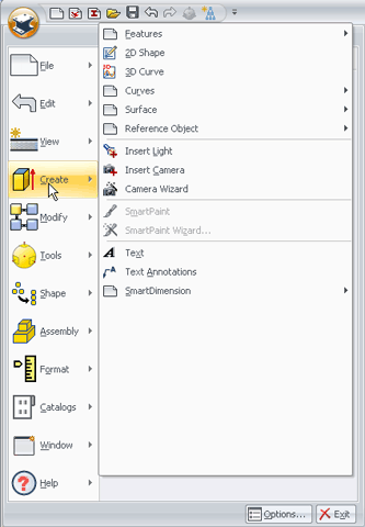
Fluent Menu Button Interface
The Fluent Ribbon interface also supports the ability to enable individual toolbars for power users to customize the most productive user interface for their needs. Since this is the first release of the Fluent interface in IRONCAD, we provide the ability to return to the toolbar interface with a simple command switch by right-clicking in the ribbon interface area.
Updated Toolbar and Scene Browser Icons
In addition to the Fluent Ribbon user interface improvements, icons inside of the application have been update to a consistent theme with improved visibility and meaning. Command icons have been improved to help users navigate to the correct commands for the desired function. The Scene Browser icons have been updated to reflect the command actions in addition to providing a clean environment for navigating the structure of the scene.
Command Ribbon Bar improvements
Many of the command ribbons for displaying the relevant information for a specific command have been updated to provide a more flexible and powerful environment. The new command ribbons provide the user the ability to view the selections made during the command and allows for change in the selections. The command ribbons are also contextual in that they will disable functions and options not available based on the current selection.
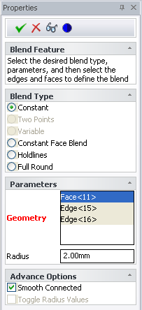
Command Ribbon Bars
Detailed Part Design Improvements
Innovative/Structured Part Design Creation Options
IRONCAD 2009 "Next Generation" provides the ability to design different types of parts in a single modeling environment to fit the needs of the designer and the task at hand. Each part design types have unique behaviors that benefit different aspects of design as follows:
Innovative Part Design - Innovative Part Design allows users to build a non-restrictive history of features that make up the design aspects of the part. Although it has a history of features, the system allows the user the ability to dynamically change the history order without inverse effects of feature dependency rules and restrictions. SmartUpdate technology within Innovative Part Design aids the users by intelligently managing the feature history giving predictable results when changes are made by the user. Innovative Part Design also provides a level of flexibility by allowing the user to refer to geometry elements regardless of the history order in which the geometry appears. This flexibility allows the user to work as if they were working with a physical object in their hands eliminating rules implied by the system.
Since the Innovative Part Design supports features, users are able to add specific design rules to create parametric design intent. The advantage in this approach is to apply intent when needed allowing the user to place only the critical design intent during their design process without the need of system applied rules that may not apply to their design task.
In addition to the non-restrictive history based capabilities, users are able to directly edit the geometry regardless of the underlying definition of the feature. This capability allows the user to work on imported data containing no feature information directly as well as the Innovative Parts with feature information. Unlike other direct geometry systems, IRONCAD will maintain the feature design information that is not effected by the direct geometry modification, creating the only application that can truly support a mixed feature environment.Structured Part Design - Structured Part Design is a history-based structure of features that build the design following a intended design order determined by the user. This part design allows the user to define a rigid sequence to their design that can be predictably changed based on the intent provided by the user. During the design process, users can "rollback" to any stage of the design to edit the feature definition at the stage in which the feature was created. After this modification, the remaining features will update accordingly to the changes applied.
Structured Part Design also provides a powerful multiple body capability to aid the user in designing the part that could be made up of 2D Sketches, features, 3D curves, and surface features. Using command tools such as Boolean, users can combine the multiple bodies as a feature operation event which allows the user to fully edit the underlying definition at any stage to alter the design.
In addition to the feature-based design, users can apply direct modeling edits which can be additional feature of the design or they can convert the design into an Innovative Part Design to have additional flexibility in modifying the design regardless of the feature order.
IRONCAD provides the ability to create a new scene environment that can contain a mixture of parts resulting from different design types. There are two different methods to determine which part type to create:
Status Bar Part Design Toggle - Located on the status bar, users can designate the part type that will be created when creating new features through drag & drop from catalogs or when starting new features/sketches. This approach is used primarily when designing in a bottom-up design manner to build the parts and assemblies of the design.
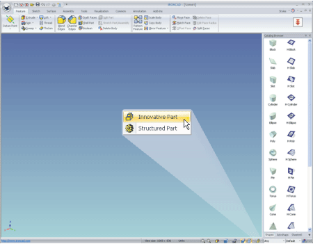
Part Toggle Type
Create Part Command - Located on the Assembly Ribbon Tab, users can select to create an empty part into the scene environment in which the part type is determined by the current status bar part type setting. This command is useful in creating a top-down assembly structure. It allows the user to build the entire structure from the start, then complete the design information for the parts at a later stage.
Create Part Command
Structure Part Design - Multiple Body support
Structured Part Design supports the ability to create multiple bodies of features, curves, and surfaces under a single part that can maintain reference associations amongst each body and can be used downstream to combine and build the final solid model. This capability gives the user the ability to create features under a single part that can refer to other feature information (for parametric relations) and allows the full editing of the definition of the feature after operations such as boolean and trim are performed. For example, users may create surfaces under a structured part that are related to the base geometry definition. After the surface is created, they may use a trimming operation to remove material from the solid geometry. If the base geometry is modified, the surface and resulting trimming operations will automatically update to maintain the design intent. Multiple bodies under a single part is a convenient way to represent an intermediate stage in the part design.
Structured Part Design - Feature Behavior Rules
Structured Part Design is designed to take advantage of many Innovative Part Design concepts like handles, catalog drag & drop, and TriBall positioning. However, certain rules are applied as follows:
TriBall Feature Behavior - The TriBall positioning tool can be used to position features that do not have any association references applied to the feature sketch. This allows for quick positioning of non-associated features. Once a feature's sketch contains either positional sketch placement references or constraints to 3D elements, the TriBall positioning will become inactive. In Structured Part Design, design intent and references are applied to maintain consistent updates and changes in the design. Once this design information is applied, the free-form position capabilities are not valid.
Feature Linking - Linked feature support is not valid in the Structured Part Design. The Innovative Part Design linked feature concept allows the user to place related copies of the features in various locations on the part. However, this concept is not valid for a rigid structure where the user will need to define intent for the placement of the features so that modifications can consistently maintain when they are made. This is the current behavior, however we are always investigating ways to improve productivity in the future.
IntelliShape Handles - IntelliShape handles continue to be part of the IRONCAD flexibility in Structured Part Design for catalog based features. However, sketch based features will only support "Profile" handle editing (no access to sizebox handles).
Catalog Drag & Drop - Catalog Drag & Drop functionality is still valid in the Structured Part Design. Users can continue to drag & drop features to and from the catalog.
Anchor Behavior - Anchors are created within the Structured Part Design, however the "Attach to Surface" behavior is not supported. The "Attach to Surface" behavior is a temporary constraint behavior that is powerful in the Innovative Part Design, but is not a valid constraint method for the Structured Part Design. The "Attach to Surface" behavior however can be achieved through feature profile associations.
Structured Part Design - Reference Association Rules
Structured Part Design is based on a rigid ordered history structure to enable an ordered design intent in the design. This design concept implies that reference associations in the features can only apply to geometry/features that are recorded prior to the feature being edited. Reference associations cannot refer to geometry that is created after the feature in the structure and cannot refer to elements outside of the part (this is a planned enhancement to support in a future version). This design rule makes it easy to enable predictable and understandable design intent into the feature design and updating process. Warning messages will appear when a reference association has been lost due to changes to the design to help rebuild the model to the desired intent.
Structured Part Design - Feature Rollback Support
Structured Part Design is based on a rigid history structure order which provides the ability to rollback to any given stage of the design. For example, the user can roll-back to a previous state of the design and insert additional features or make modifications at that stage of the design. In addition to this manual flexibility, the system will automatically rollback when the used edits the feature definition to provide users with a clear understanding of the design state when the feature was created and providing a clear understanding of the elements available at that stage to reference.
Active Part Design Mode
A new option is available to set a part as
the active part in the scene environment. When enabled on a part, all
command actions will apply to the selected part and all other parts in
the scene will dim as transparent and become reference parts. This allows
the user to create new features in the scene environment applied to the
active part at any location (even selecting an existing part). Also, this
allows the user to select and refer to other parts in the environment
without editing or modifying the non-active parts. To enable a part as
active, users can right-click on the part to enable the option. Also,
users can set the default behavior for parts when using the create part
command to be active, non-active, or prompt.
This capability is most useful in Structured Part Design when creating elements like surfaces, sketches, and 3D Curve in which you wish to apply as features or additional bodies of the part (instead of new parts).
Edit Feature Options Support
New capabilities have been added to allow the user the ability to edit the feature definition options for features such as Extrude, Spin, Sweep, and Loft. Users can edit the options to change the sketch used in the operation and other definitions like the extrusion type and settings. This capability is useful when incorrect settings were initially selected or if design intent changes occur to the original definition of the feature.
Structured Part Design - Datum Features (Plane, Axis, and Point)
Within the Structured Part Design, users can create reference objects such as datum plane, datum axis, and datum point objects. These datum objects are fully associative to the objects that they are referencing during the creation providing the ability to maintain update associations when geometry changes. In addition, features that refer to these datum objects will be fully associative and will update when the datum references change. These datum objects can be used to aid in defining and maintaining positional locations for features in your design. Examples of when these datum references may be used include:
Planes are used in lofts and sweeps.
Planes can be used to create offset references for sketches and 3D curves.
An axis is used in a circular pattern.
Points to define 3D Curves or positing of sketch planes.
Note: Only available in Structured Part Design
Structured Part Design - Delete Body command
Since the Structured Part Design supports the ability to create multiple solid, surface, and curve bodies under the part, users may need the ability to delete a body. For Example: A user may create a surface body that is referring to the solid feature definition. Then another feature may be created that refers to that created surface using a command like Extrude to Surface (to shape the extruded feature result). At this point, the surface body is not needed to be visible since the user only wants to use the surface to shape the solid extrude feature. The Delete Feature will allow the user to remove the body (surface in this case) as another feature in the history order so that all the references are maintained but the body is not displayed.
Note: Only available in Structured Part Design
Structured Part Design - Move Face Feature command
During the Structured Part Design process, it may become necessary to directly move a face of the geometry which may not be possible by editing the underlying feature definition. The Move Face command allows the user to translate and rotate a face using input vectors or by using the TriBall in a Free Move. Unlike the Innovative Part Design Direct Face Move Command, the Move Face under Structured Part Design will become a feature in the history order. This is beneficial in that you can update the original feature data and the Move Face feature will replay and update accordingly to maintain the design intent used to make the move face operation.
Note: Only available in Structured Part Design
Pattern Feature Command
Creating patterns of features is a common task in design. IRONCAD offers two different types of patterns, each providing a unique value.
TriBall Pattern - The existing TriBall pattern is a quick method to create a parametric pattern using the positioning power of the TriBall. This pattern only controls the number, distance, and location and is using the feature linking capability. It supports linear, circular, and bilinear patterns, however it is only a single feature pattern (no support for pattern of pattern). Note: Only available in Innovative Part Design.
Pattern Feature Command - A new pattern feature command has been added which provides performance improvements, direction reference relations, pattern of pattern, supports blend/chamfer/draft in the pattern result, and supports the feature extrude to operations (For Example - Extrude to Surface can be maintained in the patterned features). The new pattern is an editable feature that allows the user to refer to edge/vectors to define the direction, axis, or path in Linear, Bilinear, circular, or edge path patterns. The reference is maintained when the geometry is modified in which the pattern will update to reflect the change in the reference modification. The pattern is based on a new algorithm that provides fast updates when the geometry is modified and benefits users with many feature patterns.
Scale Feature Command
A new command is available to scale the part while creating an editable scale feature. This scale feature applies a scaling factor to part containing all the features prior to the scale feature in the structure. Users can apply a uniform scale or scale about a defined axis.
Mirror Feature Command
A new command feature has been added to mirror feature geometry using a reference plane/face. The mirror feature command allows the user to define a reference plane and the features to mirror about the reference plane. Changes to the reference plane location or features will update the mirror feature to maintain the design intent. This feature is different from the TriBall mirror in that the reference plane is maintained and can be updated/edited.
Copy Body command
The Copy Body command allows the user to select parts or bodies from other parts and copy them as a single b-rep feature into the active part structure. This is useful in when you need to reuse data from other parts or you need to copy only a portion of an assembly into the current active part. The copy body is a copy of the original part/body and is currently not a linked reference.
Ruled Surface Normal to Surface Creation
The Ruled Surface has been improved to support a new type called Normal to Surface. Users can select a 3D Curve/Edge and a surface to define a ruled surface that is normal to the selected surface at a distance. In Innovative Part Design, the resulting geometry is a non-editable surface feature. In Structured Part Design, the feature definition can be modified to change the selected references.
Structure Part Design - 3D Curve/Surface Reference Associations
3D Curves and Surfaces have a distinct advantage when created within the Structured Part Design. 3D Curves can be created by referring to points of 3D elements of the part. When the part is modified, where these elements change or re-position, the 3D Curve will automatically update to the change. In addition, a 3D Curve created from a geometry edge, will update its geometry when the geometry edge is modified. Surfaces inherit the same capability in that it will update if the surface uses these 3D Curves that refer to these geometry elements. They can also refer directly to the geometry elements as well and can update when these elements change. This capability provides a powerful method of driving curves and surfaces within the Structured Part Design.
Note: Only available in Structured Part Design
Rebuild/Regeneration Failure Notifications
A Rebuild/Regeneration failure notification mechanism has been added to help resolve failures in the feature definition. Users will be provided with options during these failures such as edit the feature (s) that are failed and ignore and continue the process. This is helpful in defining and locating the failure areas as well as providing a method to correct the issue at the time of the failure. An example for this could be a failure in a sketch where a sketch curve is projected from a 3D element that no longer exists or has changed its type.
Face/Edge/Vertex Selection List Capability
During commands that require selection of a Face/Edge/Vertex and in the general environment, users can "Ctrl-Alt - Left-Click" to access a selection list of faces, edges, and vertices based on the current location. This allows the ability to select entities that may be behind the current geometry in the viewing direction. Commands that support this capability include Blend, Chamfer, Shell, Draft, Pattern Feature, Mirror Feature, Move Face Feature, and other commands that require this selection level. Users can also access this capability to select faces, edges, and vertices in the scene prior to starting commands.
Detailed Sketch Improvements
Sketch Ribbon Tab Navigation
Within the new Fluent Ribbon user interface improvements, users will find the Sketch Ribbon Tab that contains all the necessary functions for creating/editing the 2D sketch. This tab is automatically invoked when entering the sketch editing mode and provides a central location for the user to work in the sketch. In addition, the previous complete/cancel dialog has been removed and located in the Ribbon Tab to avoid disrupting the user interface or causing clutter in the scene environment.
Sketch Placement Advance Options
Additional advance options have been added to the 2D sketch placement property browser to control the placement and selection references. Users can view and modify the selected reference when placing the 2D Sketch by using the "Selected Geometry" edit control which allows the user to view, delete and clear selection (used in placement options like 3-point, parallel to face at point, etc). "Advance Options" allow the user to define the origin point location and X-direction and maintain this reference (useful when picking a plane/face as the reference). The 2D sketch automatic determination of the placement type based on the users picking location can be disabled to allow the user the ability to pre-determine the exact placement type. In addition, options are available to automatically finish the 2D sketch placement when all the conditions of the picking location are complete (this can be disabled as well for additional control to the advance options).
Structured Part Design - Reference Associations
Structured Part Design
is designed to support reference associations to apply design intent to
the design process. When creating 2D Sketches in this part design, references
can be created to the geometry selected in the sketch placement operation
(excluding the "Point" placement). For Example, when a user
places a 2D sketch that refers to a plane/face, the sketch will update
its location when the plane/face is modified. Another example would be
the 3-Point placement in which the reference are maintained and updated
when the reference geometry is modified. To enable the reference, users
can select the "Fix to Reference" option in the sketch placement
browser.
Automatic relations will be created for features in the Structured
Part Design during drag & drop from the catalog when the features
anchor is located at the origin of the sketch. This is useful to automatically
create shapes like custom holes that are referring to a center point of
an arc allowing it to be maintained when the geometry is updated.
Note: Only available in Structured Part Design
Improved Interactions Within Move, Rotate, Scale, and Pattern commands
New behaviors have been added to the Move, Scale, Rotate, and Pattern sketch commands to help navigate the selection mode and drag modes. Radio button have been added to denote the mode the user is currently working within. In addition, users can right-click to change between the selection and drag mode. This provides a productive method to allow the user to quickly select and then right-click to change to the drag mode behavior. Another improvement has been added to automatically place the user in the drag mode when entering the command when geometry is already pre-selected. User can also right-click and drag within the drag mode to invoke the existing move/copy dialog behavior providing power users the flexibility to maintain the use of existing behaviors.
Right-Click Drag Support for Move/Copy Operations
Users can now right-click and drag on 2D Sketch geometry in the sketch edit mode to move/copy to a specified distance. Users can take advantage of the SmartSnap technology to automatically place the move/copy in the desired location. This capability improves productivity by eliminating the need to enter a command to create the precise move/copy.
Enable Parallel/Orthographic Camera Settings in Edit Sketch Mode
Under the Options/General tab, users can enable a new camera behavior when entering the 2D Sketch editing mode. In many instances, users want to work in the 2D sketch in an orthographic viewing direction versus a perspective mode used in 3D visualization. This new option automatically changes the camera to orthographic when entering the sketch edit mode eliminating the need to toggle on/off the perspective camera. When the user exits the sketch editing mode, the camera will return to perspective for the 3D visualization.
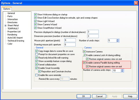
Enable Parallel Camera Option Setting
Direct Dimensional/Constraint Relationships to 3D Within the Sketch
Within the 2D Sketch editing mode, users
can create constraints that directly refer to 3D geometry elements through
automatic projection references. SmartDimension can be placed from sketch
curves to 3D Geometry to create the necessary design relationships to
drive the sketch. Also, constraints such as coincident, parallel. perpendicular,
tangent, concentric, colinear, and midpoint can be placed from sketch
geometry directly referring to the 3D geometry.
Note: Only available in Structured Part Design
Linear and Circular Pattern Constraint and Dimension Support
When creating a linear or circular pattern
in the 2D sketch environment, users can now select options to add pattern
constraints and dimensions. These constraints can be edited to redefine
the pattern information and allows the user to define the pattern constraints
to be used in parametric conditions.
2D Formula Curve Creation support
Formula curves now can be created within the 2D Sketch editing mode in addition to the 3D Curve mode. A similar dialog found in the 3D Curve Formula Curves can be accessed in the sketch mode to create and store formula driven curves.
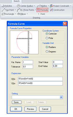
2D Formula Command and Resulting Dialog
General 3D Design Improvements
Innovative Part Design - Direct Face automatic Selection
New automatic face selections have been added to the direct face modification tools to aid in user selections. User selection options such as perpendicular, parallel, coplanar, equal radius, concentric, tangent neighbor, and tangent chain are available to control the selection to the intended geometry. This automatic selection helps aid the user in making direct modifications that would have previously required the user to manually select geometry to make the intended changes. This capability is at a selection level so the user can see the automatically selected geometry and it allows them to dynamically change the selection types or disable the selection. The automatic selection options are displayed in the property browser within the direct modification commands, imported or combined b-rep shape handles, and on direct face driving SmartDimensions.
Note: Only available in Innovative Part Design
Innovative Part Design - Automatic TriBall Activation in Direct Move Face Contextual Operation
During direct face modifications in Innovative Part Design, a common task is to modify the faces using the TriBall positioning tool. To improve productivity when the direct face modification command is activated while faces are selected, the TriBall will automatically enable allowing the user to directly change the position and apply the command. This eliminates the extra step in activating the TriBall manually.
Note: Only available in Innovative Part Design
Innovative Part Design - Direct Face Modeling Smart dimensions
SmartDimension have been enhanced to support the ability to modify geometry directly by driving the face position. Selecting to the face level, users can now apply SmartDimensions on the face and refer to other geometry to define the desired distance measurement. Editing the dimension, users can drive the face position to modify the geometry using the direct face modification capability. When Direct Face Modeling SmartDimensions are created, a new folder category will appear in the Constraints folder within the Scene Browser called DFM Dimensions to clearly denote the new SmartDimension type. Currently, this capability is only used for direct driving but will be enhanced in the future to support parametric relationships.
Note: Only available in Innovative Part Design
Imported/Combined B-rep Direct Face Radius handles
Imported and combined b-rep data inside of the application can display handles in the same manner as IntelliShape features. These handles enable the user to directly modify the imported or b-rep data without the need for features. A new handle has been added to circular face geometry to allow the user the ability to dynamically drag to change the radius size. Users can now position and change the circular geometry using these handles.
SmartDimension Display Information
SmartDimension have been updated to display the driving object when the SmartDimensions are modified. A blue arrow indicator denotes the face/feature/part/assembly that will change when the SmartDimension value is modified. This helps the users understand how the geometry will modify when the values are modified.
Multiple Select SmartDimension Delete Capability
User can now multiple select SmartDimension within the Scene Browser and delete the entire selection. Previous versions only supported single selection delete capabilities.
SmartAssembly Improved Connection and Display capabilities
The patented SmartAssembly capability has been improved once again to strengthen the powerful behavior. The following improvements have been performed:
Attachment Point Display Names - When selecting and mousing-over attachment points, the attachment point name will display. This aids the user in locating the desired attachment point for design or modification operations.
Attachment Point Indicator Display Improvements - The attachment point indicator has been visually improved to display thicker and larger to help denote the Z & X axis for the user. This makes it easier in positioning and orienting the attachment points when setting up attachment locations.
Neutral Connector Designation - Previously the SmartAssembly connections referenced male (_M) and female (_F) connection designators. A Neutral (_N) designation has been added to allow the flexibility in creating connection options. This also makes it easier in defining the connection by not needing to define the male and female ends of the components.
Default SmartAssembly Attachment Designation- User can now define the default connection attachment point for a given attachment name. This allows the user the ability to define the default connection to drop and connect to. For example: A component may have X number of attachment points named Attach_M. Previously, when dropping onto this component, the SmartAssembly would connect to the nearest attachment (Attach_M) for the Attach_F connector. Now the user can define one of the Attach_M connectors to be the default designator. This will allow the SmartAssembly to always drop to this connector even if another attachment is near the drop location. The default designator is denoted by an asterisk located to the right of the gender designation (Attach_M*) and can be used on multiple attachment names (in this case, the drop action will find the nearest attachment connector and then locate the default designator).
Right-click Display List Connection Options - Users can now right-click and drag & drop SmartAssembly components from the catalogs and display a connection list options dialog. This dialog will allow the user to see all the available connection pairs and allow them to preview the connection by selecting a connection pair in the listbox before applying the operation. Left-click and drag & drop will use the default nearest or default designator connection method.
Catalog Part regeneration Capability
A new option has been added in the Catalogs to regenerate the part/assembly data. This is useful to migrate old catalogs with new data available in newer versions of IRONCAD. Within any catalog, right-click and select "Regenerate" to activate the command. This will open each part/assembly in the catalog and re-create the contents using the current version of the application. Users must save the catalog to maintain the updated information.
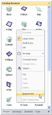
Catalog Regenerate
Catalog Export/Import Utility
A new add-in utility has been provided to allow user the ability to export parts/assemblies stored in catalog out to a folder. Once the data is saved to individual scene files, users can update the contents in the application as independent files. Once complete, the user can import the newly modified files into a new catalog using the import capability. This is useful when you need to change information stored in IRONCAD. This add-in utility will be made available to customers in the IronCAD community.
Design Variations Image Compression Support
More and more users are taking advantage of the powerful capability of the Design Variations. Based on this increasing usage, the Design Variation capability has been improved to reduce the overall size of the data stored. The Design Variation preview images that can be created for each variation has been improved to use a compressed PNG format reducing the data size and memory footprint significantly when many Design Variations are added to the scene or catalog. Using the new Catalog Regeneration command, you can take advantage of this improvement even in your legacy Design Variations stored in catalogs.
Automatic File Backup Support
Backup capability of Scene files (including links) has been provided in this release. Users can specify the backup file directory under the Tools/Options/Directories. This capability allows the user to store backup versions of the files while they are working as a fall back to recover data in the event of corruption.
Reverse Wheel Zoom Camera Option
A new option in Tools/Options/Interaction has been supplied to control the camera direction when zooming using the mouse scroll wheel. Users can reverse the camera direction to suite the needs of the design.
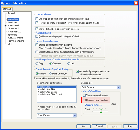
Reverse Mouse Wheel zoom Option
Background Fixed Aspect and Location Image Options
Users now have options to place 2D images in the background with a fixed aspect ratio and a user set location. This allows users to place standard company images in templates or create background images that can be used for realistic renderings.
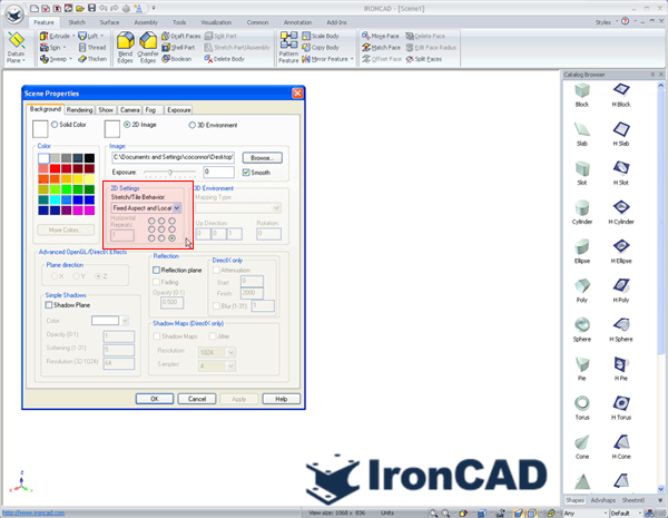
2D Image Fixed Aspect and Location Settings
Advance OpenGL/Direct3D Mipmapping Support
Mipmapping support has been enabled for the Advance OpenGL/Direct3D rendering mode. Mipmaps are pre-calculated, optimized collections of images used with textures, intended to increase rendering speed and reduce aliasing artifacts. In simple terms, it is basically a way to provide a level of detail on textures to increase performance and visibility. For Example: When enabled, small textures will drop from the view (providing a single color) when zoomed out on a model. When dynamically zooming in, the texture will begin to appear. Without mipmapping, the small textures can look distorted or cluttered due to the scaling affect.
2D Technical Drawing Improvements
Integrated "CAXA Draft" 2D Detailing Environment
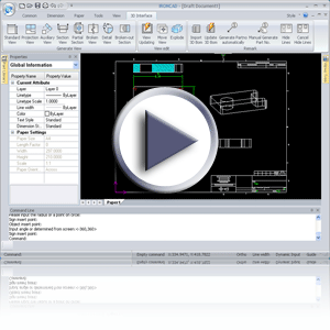
IRONCAD 2009 "Next Generation" incorporates a powerful 2D design directly embedded as a standard drafting environment named CAXA Draft. This environment has the full capability of a standalone 2D application as well as tools to detail 3D data from the IRONCAD application. Users can use the 2D environment to maintain and edit legacy DWG/DXF data or even create new 2D designs using a familiar interface found in the industry. In addition, a "3D Interface" ribbon tab is available to allow the user the ability to detail 3D designs using standard views, section views, detail views, and many others useful to layout the design data while having full association to the 3D IRONCAD data. Using the full capabilities of the 2D application, users can annotate and create bill of material information to fully complete the design.
Precise View Visibility and Performance improvements
Improvements have been made in the precise view generation to gain performance and line quality. These improvements can improve the performance 5-to-10x on larger models and can greatly reduce the memory footprint in creating these views. This is useful in design stage and when exporting to DWG/DXF. These improvements also are reflected in the CAXA Draft Environment when creating and updating drawing views.
Operating System and System Updates
Side-by-Side Application support
IronCAD design applications now provide side-by-side (SxS) isolated application support. This allows different versions of IronCAD design applications to exist and run on the same operating system as isolated applications. This capability is used to allow users the ability to upgrade to new versions while maintaining older versions of the software (useful when other applications depend on a specific version of the software and to allow testing programs/beta to be performed while an older version is still in production). Note: Even though you can run both applications on the same system, the files are not fully compatible (files saved in the newer version cannot be opened in the older version of the software).
Advanced OpenGL/Direct 3D Upgrade Improvements
Upgrades to the underlining graphical engine in the IRONCAD Advanced OpenGL/Direct 3D have been performed. HOOPS 3D from TechSoft3D has been updated to the latest version 17.1 which improves real-time graphical performance. For details on improvements in the HOOPS engine, visit http://developer.techsoft3d.com.
Subsystem Upgrades
o Parasolid™ Modeling Kernel Updates - Updates to the Parasolid kernel have been implemented. These updates include various improvements to the modeling geometry as well as support for new versions. Files up to version 21.0 can be imported and exported.
o ACIS™ Modeling Kernel Updates - Updates to the ACIS kernel have be implemented. These updates include various improvements to the modeling geometry as well as support for new version. Files up to version 19.0 can be imported and exported.
o TechSoft 3D HOOPS™ Toolkit Updates - Updates to the latest version of the HOOPS toolkit allows users to export and share IRONCAD scene files in the latest HSF format. This allows users to share data with other applications such as a viewer while taking advantage of the latest visual and performance improvements.
o Spatial 3D Interop™ Translators - Updates to the many import/export options available in IRONCAD (including IGES and STEP) have been updated to the latest versions offered from Spatial. This update improves the reliability of the import/export interoperability between CAD systems.
o CATIA™ V5 Read/Write Support - IRONCAD's add-on for CATIA V5 supports Read versions R2 through R19 and Write versions R6 through R19.
o Unigraphics™ Updates - Updates to IRONCAD's add-on for Unigraphics has been updated to support versions 11 to 18 and version NX1, NX2, NX3, NX4, NX5, and NX6.
IronCAD Viewing Applications
Freely Distributable IRONCAD Scene (.ics) Viewer
IRONCAD 2009 "Next Generation" includes a freely distributable IRONCAD native .ics file format viewer - "IC-Viewer". Users will be able to visualize, measure, preview scene part/assembly structure, hide/show part/assemblies, and perform cuts and cross sections (and more!). Based on the Advance OpenGL/Direct3D rendering engine found in IRONCAD, the IC-Viewer supports a superior rendering performance environment for viewing native IRONCAD files. The IC-Viewer can be distributed to non-IRONCAD clients to allow you to keep your team and customers closely involved in your projects. IRONCAD 2009 "Next Generation" communication tools provide many options for communication in addition to the IC-Viewer such as the IronWeb Publishing, 3D/2D PDF Support, 3D Scene Package Builder, and photo-realistic rendering/animation support.
Freely Distributable CAXA EXB Viewer
IRONCAD 2009 "Next Generation" includes a freely distributable native .exb file format viewer - "EXB-Viewer". Users will be able to visualize CAXA Draft files saved in the standard .exb file format. The EXBC-Viewer can be distributed to non-IRONCAD clients to allow you to keep your team and customers closely involved in your projects.
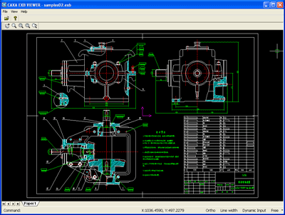
CAXA EXB Viewer Example
