|
|
|
|
New Features Introduced in IronCAD 2011 "Next Generation" |
|
|

Quick Links
Productivity Focused Improvements
Streamlined and Improved Existing Functionality
Weldment/Structural Steel Applications
General 3D Design Improvements
Core Modeling Enhancements
2D Detailing Enhancements
Communication Enhancements in Animation and Visualization
Operating System and System Updates
Productivity Focused Improvements
Quick Access Commands
A quick access hot-key has been added to provide common command functions directly in the 3D scene working space in-context of the current selection. During normal interaction in the 3D, users can activate common commands based on the current selection level by selecting "S" on the keyboard. Tool-tip commands will appear on the mouse cursor to allow dynamic access to relevant commands without the need to locate these commands in menus and toolbars. For example, users can access common sketch commands near the cursor versus spending time moving to the ribbon bar or toolbar when in the sketching environment.

Feature Level Editing Access
Various features such as the blend, chamfer and shell have been updated to allow direct editing of the values outside of the command editing mode. Users will have access to a direct input note when the feature is selected to directly change the values without entering the Feature Edit Mode.

Sketch Constraints Accessible Outside of Editing Mode
In the 2D sketch environment, users can define dimensional constraints to modify the sketch in a desired manner. In 2011, these 2D sketch constraint dimensions can be accessed in the scene outside of the sketch edit mode to allow easy access to directly drive the geometry.

Recent List Access On Start-up
Improvements to the welcome dialog gives access to the most recently opened files saving time searching or locating recent files when launching the product. This list can be adjusted to display a custom number of recent files which will also control the recent display list in the Menu Recent List Display.

Welcome Dialog Recent File List Access
Shift-Box Selecting Support
When working in an assembly environment, it is a common need to select multiple components. One method of selection is the ability to Box Select areas of the environment to select groups of components. Users will now be able to shift-box select to multi-select components for various actions. This reduces time in manually selecting individual components.

Multiple Select Selection List Support
Extending the new selection option recently incorporated, support has been added for the ability to multiple select when using the Ctrl-Alt command. When using the Ctrl-Alt selection, a dialog will appear giving users a selection list of the nearest entities to the cursor. Holding down Shift-Ctrl-Alt, you can add additional selections to the current selected group. For example: To select multiple edges on a part where some may be hidden from view: Using the Ctrl-Alt, users can select hidden edges and use the Shift-select to capture other edges on the part (to apply a blend for example).

Apply to All SmartPaint Editing
The SmartPaint "Apply to All" capability will allow users the ability to apply the changes to the SmartPaint appearance properties on all the parts that currently have the same settings. For example: Consider 100 parts in a scene and 80 of them are the same in appearance properties. User can change one of the parts SmartPaint settings and apply it to the other 80 parts in a single command. This allows the ability to setup a scene with basic rendering properties and then apply the changes to all the parts at a later stage for realistic rendering or just for better visibility.

Extrude Feature Taper Support
A new option has been added on the Extrude Command Browser that will allow users the ability to apply a side taper while creating the extrusion feature. This automatically sets the Intellishape Surface Reshaping setting without the need to go into the individual feature property pages at a later stage in the process.
Extrude Feature Taper (Draft) Setting
Streamlined and Improved Existing Functionality
Pattern Feature Support for Offset Pattern
The Edge Pattern Feature has been extended to support the ability to create an Offset Pattern. Users can place the features to pattern in the offset location and then select an edge to define the pattern direction. The pattern then will maintain the current offset location as it follows the edge direction. This improves the modeling capabilities to design more complex and related feature geometry.

Pattern Support for Sketch Driven Pattern
Adding additional control and flexibility, 2011 has introduced a Sketch Driven pattern feature. Using a 2D Sketch that is defined with points, users can drive a features position based on the sketch defined points. This allows flexibility to define irregular patterns that can be parametrically controlled by the sketch.

Scale Feature About Point Support
Enhancing the Scale Body command recently added, 2011 will offer the ability to scale about a selected point on the geometry. Originally the command used the origin of the part to scale, which may not yield the desired results. Using the scale point location, users can specify exactly where and how to scale the selected geometry.

Property Page Display and Accessibility
During the design process, it is common to access properties of features, parts, and assemblies for additional settings. In 2011, these property dialogs have been rearranged from a tab view to list view to allow easier access and to reduce mouse movement in the dialogs.
Examples of the Update Property Dialogs
Industry Focused Improvements
Sheet Metal Design
Lofted Sheet Metal Support
Support has been added to allow the creation of a lofted sheet metal part that is defined between two user specified profiles. To define the profiles, users only need to create a smoothly connected open-curve profile and the loft will automatically apply the sheet metal thickness as defined in the property browser during creation (Note: Users can use the current default stock or select from a stock list during creation). The Sheet Metal Loft in 2011 is the base stock sheet metal part and other sheet metal features such as bends, punch, and forms can be added to this stock (Note: Lofts cannot be added to bends to other stock shapes). This extends the sheet metal capabilities into additional industries that require more complex sheet metal components.

Unfold Developable Part Support
It is common to import sheet metal designs that have been created in other applications or even use standard modeling to layout sheet metal parts. Users will now have options to unfolded these parts by selecting the faces that are formed by developable surfaces (non-developable would be similar to a double-curvature surface common in lofts or meshed surfaces). During this operation, users can specify a standard stock with a k-factor and thickness or specify custom values. The resulting flat pattern contains bend-line information that can be referenced in the 2D technical drawing.

Custom Form Tool Capability
In the sheet metal industry, there are many different forms (tools that form sheet metal to create form features such as louvers, lances, flanges, and ribs.) and punch (cut) geometry used that are commonly based on company standards. In this release, users have the ability to create their own form geometry from standard solid geometry and store them into the catalogs. Once stored in catalogs, users can drag and drop these custom forms onto any sheet metal part to apply the forming shape. In addition, users can use Design Variations to drive the forms to a desired size during the creation in the sheet metal part. This extends IRONCAD’s sheet metal capabilities to meet growing standards set by companies manufacturing needs.

Associative Fillet and Chamfer Feature
Extending the current capabilities, the fillet and chamfer tools will now create automatic associations to the reference geometry that they are applied too. This allows the fillet and chamfer to support non-90 degree angled geometry and to update when the underlying geometry is modified.

Improved Unfolding Algorithm
In the 2011 release, the sheet metal unfold algorithm has been greatly improved, including support for relaxed tolerances, to support additional conditions in the sheet metal parts to return valid flat patterns. Although this new algorithm has been added, existing sheet metal parts that already have unfolded parts will maintain the current flat pattern results to maintain legacy parts. To update existing sheet metal parts, simply delete the unfolded sheet metal part and the new algorithm will be used in the next unfold operation (Note: Data that referenced the original sheet metal flat may lose its references such as dimension in drawing. Only update legacy sheet metal if required to avoid such issues).
Standard Cut and Edge Feature Geometry Supported in Sheet Metal
Included in the new sheet metal unfolding algorithm is the ability to support general modeling capabilities such as removal features and blend/chamfer features. In the past, users would be required to apply the Cut Sheet Metal feature to apply removal features in sheet metal that were beyond standard punch shapes. Due to the new unfolding algorithm, users can simple apply features such as the H-Block to the sheet metal parts to remove geometry from the sheet metal part. This allows the ability to reuse standard features that users are familiar with and allows for modification to be made easily. Note: Blends/Chamfers are only valid on the thickness edges of the sheet metal part (not valid on the top/bottom faces of sheet metal parts).

Bend-Line Call-out Display in Technical Drawing
In the 2D Technical Drawing, bend-line call-outs are now added to denote the up/down, radius, and angle values that are defined from the bend. This reduces the time spent in detailing sheet metal and is critical for applications like lofted sheet metal for manufacturing. In the 2D Technical Drawing, users will have access to the Bend-Line Call-out Style to define the text and layout rules for the bend information such as above, below, or in a leader format.

Edit Punch Sketch Geometry in the Flat
Punches applied across bends usually require editing capabilities with respect to the flattened geometry of the sheet metal in order to define the position. In 2011, users will have the ability to edit the punch sketch profiles with respect to the adjacent connected bend segments in a flattened mode, allowing users to reference and dimension the placement of the punch to the flattened geometry.

Weldment/Structural Steel Applications
Trim Feature
The trim feature has been drastically improved in the feedback of the user interface and in capabilities not only for trimming surfaces but as well for body-to-body trims. For general trimming, the command browser has been updated to improve selections and highlighting the resulting trim. In addition, it supports trimming by surface, face, plane, and by curve (also supports the ability to automatically extend the curve on the surface naturally if the curve does not fully cut the trimming surface). For body-to-body trimming, users can select to trim a body by another body (Solid body trimmed by another solid body) or selected set of faces. This is common in the structural steel applications or weldments when two elements intersect (consider a steel frame with a cross-member element).

BOM Level Access to Single Feature Angle Information
When creating structural steel elements (for example: individual beam elements), users will often apply taper angles to the start and end segments of the element. This information is critical for the detailing and manufacturing. In 2011, single feature parts will have the ability to access the start and end taper angles in the BOM to help reduce the effort in manually calling out this information.

General Improvements
Core Modeling Enhancements
Rib Feature
A new feature command has been added to support the creation of a rib based on a 2D sketched profile. This feature is more advanced than the catalog rib tool in that it supports a custom profile and has behavior rules when creating the feature such as extension of the curve defined in the profile. This acts like a real feature that will appear in the scene browser and will support editing functionality of both the feature and the sketch. Users can sketch open curve segments in the profile and the command will allow the user to define the direction of the rib and the thickness as well as a taper angle.

Emboss Feature
The emboss feature allows users to define a profile and emboss it onto a selected surface or face to create a recessed or protruded pocket. This is powerful for curved faces/surfaces when it is necessary to have these embossed shapes applied.

External Reference Body
In Structured Parts, users will have the ability to save feature bodies out as an external referenced file. This is used when a design of multiple bodies are created in a structured part for in-place creation and associations where at the end of the design the bodies need to have individual part information (BOM) or extra detailed modeling. The external part created will create a non-editable feature under the part (that is updated from the original body). Users can add additional features to the part and will be notified when updates are made to the original body (to allow the user to update or not). An example of this design process could be weldments or structural steel where the bodies could be parametrically positioned and trimmed in the structured part. Users then could save out each member for detailing, BOM collection, or for additional modifications not necessary in the main assembly design.

Import Pro/E Multiple Body Support
A new option has been added in the Import Options for Pro/E files to import data stored as multiple bodies as a structured part that will maintain the body information. This is useful when working on data from Pro/E where the original designer has created multiple bodies in the parts. Maintaining this information helps users maintain the original design intent and can allow users to make modifications that maintain this intent.
Split Face Support for Curve on Surface
The split face command has been updated to support splitting parts/surfaces by a curve on the surface. This improves the overall design process by reducing the need to create solid geometry for the split operation.

Thicken Surface Support for Vector Direction
Users will now have options to define the thicken vector direction during the Thicken Surface/Face command. This is useful when the thickening feature may not be normal to the surface thicken condition.

Wrap Curve Support For Wrap Feature
Enhancements have been made to the Wrap Curve command to allow the user to select a curve or profile as a feature to wrap. This expands the capabilities to wrap entire profile geometry versus single curves and allows for more complex cases to be supported such as wrapping a profile of text.

Wrap Curve Input Support for Rotation
When wrapping a curve to a surface, users now have the ability to define not only the wrap location but the rotational effect of the wrap curve (this option can be viewed in the Wrap Feature Support video above). This provides additional control in producing the wrapped curve result.
Extend Surface Support for Multiple Edge Selection
The extend surface command has been improved to allow for multiple curve selections in the operation. Enabling this option allows for multiple edges on a surface to be extended and merged in a single operation reducing the overall process in extending edges of a surface.

2D Detailing Enhancements within the Integrated CAXA Draft Environment
Import/Export Support for DWG/DXF 2010
Import and Export of DWG/DXF will now support the AutoCAD® 2010 format in both the detailing environments as well as the sketch environment. This extends the data transfer capabilities with industry standard formats.
Line Type Text File Editing Support
Users can define custom line types to be imported into the environment to be used in curve creation. This standard format can be leveraged from industry standard files (*.lin) or users can manually create custom line types.

External References Supported
In 2011, users can attach drawings as References to drawings. References can be other drawings or raster images such as digital photographs or scanned maps. Users can attach References to multiple drawings at the same time. Conversely, you can attach multiple drawings or images as References to a single drawing. All references can be managed in the External Reference manager to gain an overview of the references in the drawing and their reference type.

DesignCenter For Managing Drawing Content
With DesignCenter, users can organize access to drawings, blocks, hatches, and other drawing content. Users can drag content from any source drawing to the current drawing. Source drawings can be on a local computer or on a network location. In addition, if users have multiple drawings open, use the DesignCenter to streamline the drawing process by copying and pasting other content, such as layer definitions, layouts, and text styles between drawings.
With DesignCenter, users can
-
-
-
-
Browse for drawing content such as drawings or symbol libraries on a local computer or on a networked drive.
-
View definition tables for named objects such as blocks and layers in any drawing file and then insert the definitions into the current drawing
-
Create shortcuts to drawings and folders that may be accessed frequently
-
Add content such as xrefs, blocks, and hatches to a drawing
-
Open drawing files in a new window
-
-
-

Hide By Block
A new option has been added to blocks to support the ability to hide by the blocks boundary. Any curves that pass through the blocks boundary will automatically be hidden when the option is enabled.

Dimension Support on User Created Center Lines
Support will be added to dimensions to allow users the ability to create dimensions between center lines that are added to 3D projected drawing views to other geometry including other center lines in the drawing (from non-projected geometry). The dimension is maintained and updated when changes are made in the 3D or in the 2D environment.
View Name Indicators and Settings
When positioning views during the standard view creation process, indicators will appear in the status bar to help denote the view being placed (view name). In addition, users can dynamically change the view name during the creation in the instant command ribbon bar that displays during the view creation.
Improved Annotation Associations to Projected Views
Many annotations have been enhanced to support associations to the projected views such as GD&T, Chamfer, Text with Leader, Surface Finish, etc. In previous versions, some of the dimension types were not available on projected views or would not update the position and information when the 3D data was updated. In 2011, these annotation have been updated to support the 3D data association.
Item Bubble Association to Projected Views
Improvements have been made to support associations from BOM Item Bubbles to the projected 3D views. This supports connections when the view position is adjusted in 2D to allow the item bubbles to adjust appropriately.
Easier Access to Editing Functions in Projected Views
Operations such as properties of curves and hatch patterns in projected views required editing from selecting parts in the View Tree Browser and right-clicking the appropriate command. Enhancements have been made to support easier access to these common commands from the Ribbon Bar group directly. Users can select to access properties and hatch information from the Ribbon Bar and directly select the entity in the view to edit its values which reduces the complexity of these operations and speeds up the design process.

Box Select Support and Multiple Selection Support for Hide Line in Views
The hide command has been improved to support multiple selection and box selection. This improves the overall time in detailing when it is necessary to hide unnecessary information within a view.

Support Hidden Curve Dimensioning in Section Views
Users will now be able to apply dimensions to hidden view curves in section views for extended detailing in the integrated CAXA DRAFT.
Correct Angle Projection for All Related Views
View projections have been updated to support First/Third angle projection for standard views and for views that are referenced from the standard views (such as projected views).
Support Projected View Copy/Paste
Views will now support the ability to copy and paste (in the same sheet or between sheets) to enhance the ability to reuse data. Associated data within the copied view will be maintained in the newly pasted view.
Projected View Reference Location Updated to Center of Sizebox
When positioning views, the reference location is necessary for snapping and precise positioning. The views have been updated to use the overall sizebox center of the view for the view positioning handle. This allows for easier movement and alignment when arranging projected views.
Sub-Style Capabilities for Dimensions
When creating styles for dimensions, it is necessary to maintain a global style while setting sub-classes of the style. In 2011, usesr have the ability to create the sub-styles for dimensions. For example: Users can create a sub-style for linear, angular, radial, diameter, and coordinate dimension to control these individual settings as well as the global style properties for the dimensions.

Associative Hatch Setting
A new option has been applied to the Hatch to allow it to maintain associations to the standard curve geometry when updated. This option can be enabled per each hatch instance for additional control.

Ability to Define Custom Snap Settings
In the Options dialog under Aptitude, users can now define custom snap groupings that control the Snap behavior, Grid, and Object Snaps. New Snap Groups can be accessed in the quick access commands at the bottom right of the application (in addition to Intelligent, Guide, Free, and Grid) to allow quick changes in behavior on the fly improving the overall productivity for the users workflow.
Additional Control Over Coordinate System Indicators
Users now have controls to adjust the display and visibility setting of the coordinate systems created in the environment. Settings such as simplified and 2D versions, size, and color can all be specified to easily identify these indicators.

Mathematical Expression Support in Command Line
Users can type in mathematical expressions in the command line to return the calculated values for use in other operations. For Example: Users can type in a simple calculation such as: 100+2*sin(30) and hit return to have the result displayed automatically. This reduces time spent switching to calculator applications to return similar results.
Additional BOM Style Color Settings
New style properties have been added to the BOM Style to allow for color information for horizontal and vertical lines inside the BOM (including the BOM Header). This allows for more style control to define custom BOM templates.

BOM Manual Sorting Support
During the editing of the BOM, users can sort the BOM contents in ascending and descending order. In addition, users can manually arrange the BOM rows by moving the row up/down to the desired order. This helps define the layout of the BOM for downstream applications.
Double-Click Quick Access to BOM Row
Users can now double-click on item bubbles to be directed to the BOM Editing at the selected location in the BOM. This enables quick location and editing of the BOM information instead of manually attempting to identify the correct BOM row for placed item bubbles.

Customizable Default Template Support
In 2011, users can overwrite the default "Blank.tpl" file to setup custom settings. In previous versions, this template file was standard to the application and was not accessible to users for customization. Now it can be defined to meet the company standards and settings instead of setting up custom template files.
Additional Symbol Types for Datum Symbols
Additional symbol types have been added in the Datum Symbol to meet additional industry standards. User can control the frame and the arrow indicator based on the appropriate standard.

Surface Finish and Welding Symbols Support For Line Width
Both the Surface Finish (Rough) and Welding Symbols now support Line Width control for the symbols display. This increase the style formatting to meet company standard call-outs.
Ray and Infinite Line Creation Support
New line types are available for curve creation that allow users to create infinite lines and directional lines (ray). These line types can be used in the construction process of 2D geometry for example.

Override Style Indication and Delete Support
When creating elements in 2D, these elements are generally placed on defined style settings. Each individual element can be manually adjusted that override the initial style setting. The Property Browser will indicate these override styles by highlighting these changes in Red. In addition, a button has been added in the Property Browser to remove these override settings to revert the element back to the default style settings.

Options - Interaction Additional Settings
New settings have been added in the Options - Interaction control to better define behaviors in CAXA DRAFT. These options include selection previews, color settings for the selection box, command modes, and right-click command behaviors (Pop-up menus or command termination/repeat options).
Text Editor Interaction Improvements
Improvements have been made in the Text Editor to support drag and drop of text and copy/paste operations increasing the usability of the command.
Reorder Input Field Entries for Quick Access
Input fields for items such as title block attributes can be reordered for quick access to commonly used entries.

Overall Performance Improvements
Improvements have been made in the efficiency of the application including faster open/save operations, improved camera interactions, and overall memory usage of the application.
Improved 3D to 2D View Projection Performance
Improvements have been made to support better performance in the view projections speeds in the integrated CAXA DRAFT. The most visible difference will be with larger data sets when creating standard view layouts.
Communication Enhancements in Animation and Visualization
Improved Visualization in 3D Scene
New visualization improvements have been implemented in the 3D real-time environment to better communicate the product during the design and in communication without the need of full realistic rendering. Many of the improvement are applied to the DirectX and new OpenGL2 rendering modes. The following are the improvements to aid in the visualization quality:
-
-
-
-
Simple Shadow Plane Light Support - Shadow planes have been improved to support a shadow generated from a specified light direction as well as a camera relative shadow. The camera relative maintains a shadow based on the current viewing direction which always generates a shadow plane where as the specified light direction can only appear in certain viewing directions.
-
Shadow Mapping Increase Quality - The shadow mapping quality has been improved to support a high quality level (4096 resolution). This increases the quality of the shadow generated in this mode.
-
Shadow Mapping Support From Directional and Spot Lights - Shadow mapping can be generated from a single light source relative to the camera view angle which is beneficial when rotating an environment and viewing updates of the shadows. However to create a realistic rendering view, user create specific light sources such as directional lights and spot lights to provide a desired lighting condition. The shadow map command now supports the ability to derive the shadow from the scene created light sources. This is very useful when you want a quick display of shadow conditions prior to a realistic rendering process or to setup a real-time rendering result.
-
Fast Silhouette Edge Display - A new option has been added to draw a fast silhouette edge around the geometry in the environment. This effect can help provide a depth to the geometry without the need to draw real geometry edges that are not part of realistic renderings.
-
Bloom Light Effect - Bloom is a technique that provides a form of high dynamic range effect. It causes bright objects to bleed into darker ones, simulating the imperfect focus inevitable with the human eye or any other type of lens. Only light contributions based on specular, emissions or environment maps will be blurred in a bloom effect.
-
Hemispheric Ambient Light Support - To create a photorealistic effect in 3D scenes, global illumination in a scene from direct and indirect light sources can aid in the realism. However, global illumination can be expensive on the real-time rendering process. In order to mimic this affect, hemispherical ambient lighting has been added where a user can specify two colors of the light source to apply to the environment.
-
Ambient Occlusion Effects - Ambient occlusion is a general term for shading that varies when nearby objects (occluders) would prevent some portion of ambient light from reaching a surface. In other words, it can create a form of shadow areas based on objects blocking the light from reaching all areas of the geometry. This effect can quickly add a bit of realism to geometry without a large impact on the performance.
-
Real-time Reflection of Background Images - Reflections can now be seen on geometry based on the background specified in the scene. This is particularly helpful in realism when you are using environment and skybox images. Keep in mind, realistic rendering will include the reflections from geometry objects in addition to the background. However for real-time rendering, the reflections from the background can easily improve the quality of the representation.
-
3D Skybox (Cubic Map) Support - A skybox is a method for creating the illusion of distant three-dimensional surroundings in your scene. Images are applied as textures to each of the six faces of a cube with the viewer placed in the middle of the cube or skybox. Similar to the 3D Environments, the skybox can add the realism of an environment to your model. However, the Skybox has a less of an impact on real-time rendering which makes them beneficial in quick rendering results.
-
-
-

Zebra Stripe Visualization
Zebra stripes allow users to see small changes in a surface that may be hard to see with a standard display. Zebra stripes simulate the reflection of long strips of light on a very shiny surface. With zebra stripes, users can easily see wrinkles or defects in a surface, and can verify that two adjacent faces are in contact, are tangent, or have continuous curvature. Users are able to apply this effect to any specified face or group of faces.

Animation Path Support 2D/3D Curve Path
In 2011, users can make use of existing 2D and 3D curves as paths in animations. This extends the capabilities by allowing the full range of path support in animations (where as previous versions were limited to splines and lines). After adding a new animation path to a object, users can initiate the "Select Path" command under the "Extend Path" Ribbon Bar button on the Visualization Ribbon. This will allow the ability to select any existing 2D/3D Path as the animation path. Note: The animation path can only be edited to define rotation and time sequences. To change the definition of the path, the original 2D/3D path needs to be modified and the animation path will need to be recreated.

Animation Path Automatic Next In Path Placement
When creating an animation path, it is common to have a multiple segmented path from the end of one path to the start of another. In previous versions, it would require the user to create the second path and then adjust its position and timeline to achieve this state. In 2011, users will be able to click on the endpoint of one path and select Add New Path and it will automatically position and adjust the timeline to the end of the selected path. This enhancement saves time in the animation creation and helps visualize the setup of a multi-segmented animation.

Copy Animation Path To Another Part Support
Users will now have an option to right-click on an animation indicator in the scene browser and copy the animation to another part in the scene. This is useful when parts share a common path but may have variations at a different time sequences such is the case in assembly line animations.

Visual Improvement to Highlight Animation in SmartMotion Editor
While the user is in the SmartMotion Editor, selecting on the animation sequence indicators in the dialog will visually highlight the part/assembly associated to the animation to aid in communication when editing the animations.

User Interface Indicator to Denote Spin Animations
A new user interface indicator has been added to denote spin animations. Previous versions did not provide an indication that such an animation was present when selecting the shapes in the scene. The new indicator will allow the user to see that an animation is present and will allow users the ability to edit the animation properties by right-clicking.
Ability to Edit SmartMotion Properties in Scene Browser
Users can now right-click on the animation node in the scene browser to edit the animation properties of the current object. Previous versions required this action to be performed in the scene or in the SmartMotion Editor.
Remove Timeline Restrictions and Support Specified Timeline
Restrictions to the timeline animation length have been removed and the support to specify the timeline length has been added. Users can now specify the total length and the Frames Per Second in the SmartMotion properties.

Run in Mechanism Mode Animation Option
A new option has been added to the Animation Ribbon Bar to enable the Mechanism Mode while performing the animation (Mechanism Solving Only). Often, constraints are added between parts and can only be solved while in the mechanism mode. This option allows that animation to perform and solve the constraint in sequence. If users need to run in mechanism mode and wish to have collision detection, users can still enable the general mechanism mode first and then activate the animation.


General Enhancements
2D Sketch Large Data Performance Improvements
Improvements have been made in the 2D Sketch environment when large amounts of sketch geometry is present. These improvements are in the camera interactions and editing of geometry while in the sketch edit mode providing faster interactions for users.
3D Graphical Performance Enhancements
Improvements have been made in the 3D Graphical Performance to provide smoother interaction when dealing with larger data sets. Selection of parts/assemblies have been greatly improved to provide quick highlighting of the selected geometry. In addition, graphical rotation performance has been improved in conditions when geometry is selected and highlighted as well as non-selected. New options are provided to allow users to set the target frame rate of the system during camera interactions. This will automatically provide level of detail on the models to maintain a targeted frame rate during rotation. Also, interactions while in larger data sets are vastly improved. For Example: Positional operations such as translation and rotation of large selections is dramatically faster allowing for an improvement in the overall productivity in the design process.
Property Browser Update Performance
When the property browser is visible and active, improvements have been implemented to improve the updating of the browser information which enhances the selection speed in the scene environment. This improvement is especially noticable in large assembly files.
Warning Messaging on Mirrored Part Conditions
When exporting, saving as external links, saving to a catalog, and in copy/paste of mirrored parts (or parts that are mirrored due to an assembly mirror), a warning dialog will appear to inform users of this condition to avoid creating invalid parts. Options will be provided to maintain or remove the mirrored transformation based on the users needs.

Portable Tools/Options Registry Settings
Users will have a new capability to save the Tools/Options settings to a portable file. This file can be imported to other user’s machines to build a common standard among users along with the user interface XML files.

Cosmetic Thread Default Naming Convention
When creating the graphical threads on parts using the Cosmetic Thread tool, the thread name in the scene browser will automatically use the name listed in the command property browser selected by the user. This communicates the thread details clearly for users when revisiting a part at a later stage in the design.
Improved Error Messaging In Structured Parts
Improvements have been made to the structured parts error messaging when failures or lost references occur. Additional details and a better presentation of the conditions have been updated in the resultant dialog.

Visual Improvements for Failure or Warning Conditions
Changes to the scene browser display has been implemented to better communicate status information for features and parts when a failure or invalid states occur. New icons next to the features and text color identification have been added to easily detect these conditions.
![]()
Preview Improvements in Additional Feature Commands
In 2009, command previews were updated to better visualize the results of command operation. Additional improvements to other commands such as the Fillet Surface, Untrim Surface, Etc have been made in 2011 to extend this improved communication.
Automatic Unhide of Hidden Sketches in Structure Parts on Feature Delete
When a feature has been deleted in structured part that was built from a 2D Sketch, the hidden sketch will automatically unhide to allow users to access it directly in the scene environment for new operations.
Enable Scene Browser Open Automatically Default Setting
The default setting in the Tools/Options has been changed to automatically show the scene browser in new windows for new installations of the application. This helps users identify with the environment of the application when first introduced.

Disable Visual Load Default Setting
Default setting in the Tools/Options has been changed to disable the visual load operation in new installations of application. In normal conditions, many of the assemblies and parts loaded in the application do not require the visual loading preview. Therefore the default has been changed to accommodate the normal practices in the application.
Disable Resize and Rearrange Views Default Setting
Default setting in the Tools/Options has been changed to disable the automatic rearranging of the views when new views are added in the IRONCAD drawing environment for new installations of IRONCAD. In many instances, uses add multiple views to a drawing. After creating and positioning these views, users normally prefer that the views stay in the original settings when new views are added. This behavior has been set as the default.
Support for User Input of SmartDimension Font Size
Users will now have the ability in the Tools/Options to define the font size for the SmartDimensions in the 3D environment for better visibility on individual display settings.
![]()
Find Reference Display Option
A new option has been added to find and display linked references in the currently opened file. Located in the File Menu, users can access a list of external links and perform operations such as unlink. This list provides a overview of the scene so that users can manage files when moving from different directories or machines.
Remove Duplicate Overlapping Lines in Sketch Command
A new command has been added to the sketch to remove duplicate overlapping lines in the sketch. This command is useful in imported data from other applications. When in the sketch command, users can access the command from the menu under Tools - Edit Sketch. Once enabled, simply box select the curves on the sketch and hit enter to detect the duplicate lines. The command will highlight and list the elements that will be deleted by the operation.
Display Option to Disable SmartDimension Display
New options have been provided to not display SmartDimension on parts/features when they are selected. Previous versions would always show the SmartDimensions when selecting to the owner level. In some cases, it is not necessary to show these relationships and an option has been added for this support.
![]()
Operating System and System Updates
Advanced OpenGL/Direct 3D Upgrade Improvements
Upgrades to the underlining graphical engine in the IRONCAD Advanced OpenGL/Direct 3D have been performed. HOOPS 3D from TechSoft3D has been updated to the latest version 18.13 which improves real-time graphical performance and visual quality. For details on improvements in the HOOPS engine, visit http://developer.techsoft3d.com.
Subsystem Upgrades
o Parasolid™ Modeling Kernel Updates - Updates to the Parasolid kernel have been implemented. These updates include various improvements to the modeling geometry as well as support for new versions. Files up to version 22.1 can be imported and exported.
o ACIS™ Modeling Kernel Updates - Updates to the ACIS kernel have be implemented. These updates include various improvements to the modeling geometry as well as support for new versions. Files up to version 21.0 can be imported and exported.
o TechSoft 3D HOOPS™ Toolkit Updates - Updates to the latest version of the HOOPS toolkit allows users to export and share IRONCAD scene files in the latest HSF format. This allows users to share data with other applications such as a viewer while taking advantage of the latest visual and performance improvements.
o Spatial 3D Interop™ Translators - Updates to the many import/export options available in IRONCAD (including IGES and STEP) have been updated to the latest versions offered from Spatial. This update improves the reliability of the import/export interoperability between CAD systems.
o CATIA™ V5 Read/Write Support - IRONCAD's add-on for CATIA V5 supports Read versions R2 through R20 and Write versions R6 through R20.
o PTC Granite™ Update - IRONCAD's add-on option for the PTC Granite has been updated to the latest version supporting version Wildfire 5.0.
o Unigraphics™ Updates - Updates to IRONCAD's add-on for Unigraphics has been updated to support versions 11 to 18 and version NX1, NX2, NX3, NX4, NX5, NX6, and NX7.
New and Updated 3rd Party Applications
CADENAS "PARTcommunity" - Free CAD Models for IronCAD Users
CADENAS GmbH, a leading provider of strategic parts management solutions, and IronCAD have announced the immediate availability of a free exclusive online parts library, directly accessible from the IronCAD Design Collaboration Suite user interface.
IronCAD users can launch the specific PARTcommunity online library by using a ribbon bar button inside the new 2011 version of the IronCAD Design Collaboration Suite products. Directly browse catalogs or use a powerful search engine for cross-catalogs searches based on the dimensions or other technical properties of the part attempting to locate. After selecting a part, users have access to a real-time 3D preview and a summary of all its Bill of Materials (BOM) attributes. Users can then download the desired part to load into the IronCAD Design Collaboration Suite products to increase design productivity and reduce time to market by leveraging the supplier content directly into the design.
The IronCAD PARTcommunity can be accessed directly from within the IronCAD Design Collaboration Suite 2011 products. Download the CADENAS Strategic Parts Management PDF for more information about the product.
NEi Nastran
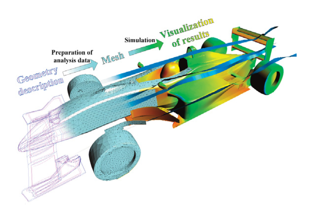
NEi Software, a world leader in CAE innovation and provider of NEi Nastran, a powerful, general purpose Finite Element Analysis (FEA) tool, and IronCAD have announced the exclusive availability of NEi FEA. NEi FEA is a powerful Finite Element Analysis application that has been designed as a universal, adaptive and user-friendly graphical user interface for geometrical modeling, data input and visualization of results for all types of numerical simulation programs. Keeping cost in mind, NEi FEA still offers an abundant resource of tools for your finite element needs. NEi FEA can be directly initiated from within the IRONCAD interface which will pass the selected part/assembly to the NEi FEA interface to process the simulation.
NEi FEA can be accessed and downloaded from the installation media on the IronCAD Design Collaboration Suite 2011 DVD. Download the NEi FEA PDF for more information about the product.
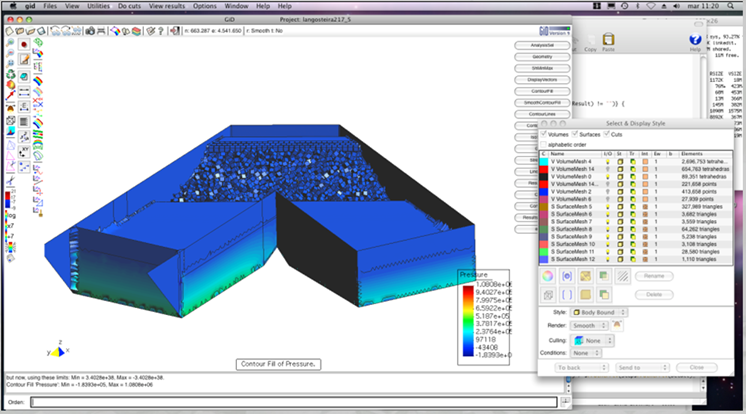
GoSimulate by Enmesh - Interactive CAE Simulations
Enmesh AB, the providers of GoSimulate - Interactive CAE Simulations, and IronCAD have announced an exclusive partnership providing GoSimulate Lite free to IronCAD users. The GoSimulate direct link within IronCAD puts the possibility to conduct thermal, elastic, and thermoelastic simulations at just one click away. This enables users to completely transform the design process by directly integrating CAE in each design step. Minimize assumptions and maximize the flexibly of your design by allowing continuous simulation results to drive the process towards an optimized design. No longer let your CAE software merely verify the flaws of your finished design, but let it instead guide you all the way, even from the earliest conceptual stages.
GoSimulate Lite can be accessed and downloaded from the installation media on the IronCAD Design Collaboration Suite 2011 DVD. Download the GoSimulate PDF for more information about the product.
If your needs extend to more advance needs, contact your local IronCAD representative for information about the full professional version of GoSimulate.

DesignDataDM Upgraded
Whether you are an individual, small business or large multinational, the information you create and maintain is one of your most valuable assets. For Engineers using IronCAD, working harder is no longer enough, in today’s fiercely competitive global market you must work smarter and more efficiently. Reducing the overhead and headache of managing the data will allow your engineers more time for not only reducing design time cycles but to focus on better more innovative designs. DesignDataManager (DDM) is an affordable off the shelf product that is designed to protect the integrity of your data, streamline your engineering creation and change processes and provide you with full audit tracking, in a managed and controlled easy to use environment, Securing your investment in design by protecting your Engineering IP.
With the IronCAD Design Collaboration Suite 2011, DDM has been updated with its latest version that brings hundreds of improvements in efficiency and ease-of-use increasing its productivity in the design environment. As a IronCAD Gold Partner, users automatically receive a single seat license for free that integrates fully with IRONCAD.
DDM can be accessed and downloaded from the installation media on the IronCAD Design Collaboration Suite 2011 DVD. Download the DDM PDF for more information about the product.