|
|
|
|
New Features Introduced in IronCAD 2012 "Next Generation" |
|
|
Quick Links
Productivity Focused Improvements
Operating System and System Updates
IRONCAD 2012 "Next Generation" is the next evolution of the most productive design tool in the industry today. The 2012 release focused on the existing capabilities of the application to streamline the process making the overall productivity even faster for designers. Users will immediately feel the impact of the reduction of mouse-clicks and mouse navigation travel. Furthermore, these streamlined processes bring additional flexibility and capabilities to the design process taking tedious tasks down to simple operations.
In addition to the productivity improvements, focus was placed heavily on achieving even greater customer satisfaction through continuous improvements of stability, quality, and performance of the application. This release includes over a 1,000 enhancements to the quality of the application and has improved performance achieving gains from 20% to 50% improvement.
Please browse the information below to find details and videos of the major improvements included in the 2012 release.
Productivity Focused Improvements
Direct Input for IntelliShape Handles
IntelliShape handles on features have been improved to support direct keyboard input on selected handles to increase productivity and reduce overall mouse clicks. Users can simply click on a handle or drag on a handle and type the desired value for the size. This reduces the need to double-click or right-click to edit the values.
Direct Input on TriBall Move/Rotate
Similar to the improvements on the IntelliShape handles, the TriBall Move or Rotate Move now support direct keyboard input for the values. This new capability speeds of the positioning of objects by allowing users the ability to quickly input the desired values during the move/rotate operations without having to access edit dialog boxes.
Selection Based Feedback
To help improve feedback given to users on objects selected, a new feedback indicator has been added on the selection to indicate the name of the selected object. The name will be displayed for Assemblies, Parts, and IntelliShapes in the scene. This improvement helps identify the correct selection when dealing with large assemblies and reduces the needs to search for the appropriate selection in the scene browser.
Scene Browser Shape Name Display Control
Often it is desired to set the scene browser to display a more meaningful name to parts and assemblies. Users now have the control to display both the display name as well as the basic bill of material information for parts/assemblies. Users can set the control in the Tools/Options/Parts to display the Part/Assembly Name, Part Number, and Description in the scene browser.
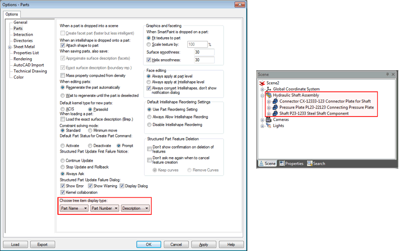
Scene Browser Name Display Settings Example
TriBall SmartSnap Orientation Handles
New intelligent behaviors have been added to the TriBall Orientation handles to help improve the learning curve and to reduce the number of right-clicks when attempting to align objects. The following new behaviors have been added:
o Drag Orientation Handle onto an Linear Edge - Behavior will automatically align the handle to be "Parallel" to the selected edge.
o Drag Orientation Handle onto a Circular Edge - Behavior will automatically align the handle to the "Center Point" of the selected circular edge.
o Drag Orientation Handle onto a Face - Behavior will automatically align the handle to be "Perpendicular" to the selected face.
o Drag Orientation Handle onto a Cylindrical Face - Behavior will automatically align the handle to be "Parallel to Axis" of the selected cylindrical face.
TriBall Reset to Copied Object
When creating copies and links of objects, often the design task would be to make a copy/link followed by positioning of the newly created object. The TriBall has been enhanced to support the ability to reset the TriBall to be active on the newly copied/linked object to facilitate this need. This option can be set globally or set individually during the copy/link command.
TriBall Lock Plane Control
The TriBall has been enhanced to support the ability to lock the Plane drag handles. This enables the ability to lock a plane and drag the centerpoint handle to a desired location while maintaining the geometry in the selected plane.
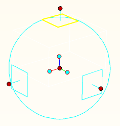
TriBall Locked Plane Support
TriBall Shift Snap to CenterPoint
When positioning objects, it is often common to position to the centerpoint of circular reference geometry. In order to reduce the number of mouse clicks when using the TriBall, a new behavior has been added when using the To Point controls (right-click and drag behaviors). While attempting to select a point, users can hold down the shift key and select a circular edge to automatically have the alignment connect to the centerpoint of the circular edge. For example: Drag the centerpoint of the TriBall to a circular edge and hold the shift key to automatically snap to the centerpoint of the edge. Another example would be to use the To Midpoint command and selecting between two points. Hold the shift key down when selecting the two points and it will locate the centerpoint in during the selection.
Ribbon Bar Customization Control
Increasing the capabilities of the Ribbon Bar UI, users are now able to customize the Ribbon Bar layout. New Tabs and Groups can be added to the display as well as editing of the default Ribbon Bar can be achieved. Users now have the ability to customize the UI to meet the desired workflow commonly used in their design process and can remove any functionality that is not often used.
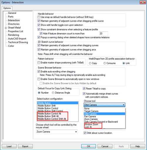
Additional Middle Mouse Button Setting options
Additional controls have been added to the Middle Mouse customization page to allow new hotkey assignments for the Look At and Window Zoom operations. Users can now assign these to new hotkey settings including Control Alt, Shift Alt, and Control Shift Alt. These new setting provide quicker access to the camera commands saving users time navigating for these commands in the user interface.
Improved 3D Constraint Solver for Bi-Directional Support
New improvements have been made to the 3D Constraint solver to aid users in positioning and modifying connected components. Dimensional constraints between parts and assemblies are now fully bi-directional meaning that either object is free to move in order to solve the desired positional change as you would expect in the real world between objects. In order to help determine which component should move, controls and default behaviors have been added to support a preferred move setting. This preferred moving object will move as long as it is free to move and is not fixed in the degrees of freedom by other objects. Advance setting are supported to allow objects within assemblies to move based on positional changes of objects outside of the assembly. This capability is powerful when objects within the assembly group change position with respect to other objects that don't necessarily belong to the same assembly which is often the case in mechanisms. Constraints added in the previous versions of the application will remain and solve in the existing method to maintain the existing behavior (which will be denoted on the annotations). New annotations added will incorporate the new behaviors added in the 2012 release.
Streamlined Positioning Constraint Tool
In order to streamline the positioning process, the Positioning Constraint Tool has been improved to get quicker input of the available constraints and to make it easier to add multiple constraints within same command operation. During selection, a Quick Access pop-up will appear to help users select the desired constraint directly in the scene without needed to refer to the command browser. After the desired constraint is selected, the command automatically will reset to allow for additional selection on the objects for new constraints eliminating the need to exit and restart the command.
Reconnection Support for Constraints
Often during the design, constraints previously added on object may need to change and/or copies of object are created where constraints information needs to be reused and adjusted. New behaviors have been added to the constraint and dimension annotations to allow the ability to reconnect these annotations to new reference information. For example: A fastener may be co-axial aligned to a particular hole. Due to the design change, a new hole is created where a copy of the fastener is needed. After creating the copy, users can now simply drag the endpoint of the previous co-axial constraint and refer it to the newly created hole to create the new alignment for the copied fastener.
Sketch Plane Placement Quick Access UI Control
During the creation of the sketch, users are presented with a command browser of the available placement options for the sketch plane. To improve this process, users can simply press the "S" key on the keyboard to display a Quick Access pop-up with the available placement options directly in the scene where the cursor is located. This option reduces the time navigating from the users display location in the scene to the command browsers providing easier input for the command.

2D Sketch Placement "S" Key Quick Access Pop-up
Penetrating Point Constraint Support in Sketch
While creating a design, it often may require a feature to be positioned by another object that passes through the sketch plane of the feature. For example: A path such as a 3D curve may pass through a sketch plane. Where this curve passes through, a feature needs to be created to define the clearance for the object that follows the path. In order to facilitate this need, a new constraint has been added to the sketch to locate sketch geometry by the location of the path that is penetrating the sketch plane. Since this is a constraint added to the sketch, when the path changes location, the sketch will update to maintain this penetrating location relationship.
Support for Linking to Sketch Outlines
New capabilities have been added to sketches to allow for the ability to create features from closed outlines while maintaining a link reference to the sketch. This capability enables users to create a driving sketch where multiple feature refer to the sketch geometry. Often this is useful when importing 2D geometry that defines an assembly or multiple parts and users wish to maintain the 2D as the primary driving object and wish to only edit a single sketch for all the objects.
Blend/Chamfer Drag Handles
Handles have been added to Blend and Chamfers during these features edit modes to allow dynamic sizing by the users. While dragging on these handles, users can directly type in the desired values to improve the design flow. In addition, users can multiple select edges and drag a handle to size the selection together.
Custom Hole Feature Utility
A new Custom Hole feature command has been added in addition to the standard drag & drop custom hole existing capability. This new command improves the performance during creation when multiple similar holes are created and during update of geometry. This new command allows users to create multiple custom holes of the same type in a single instance using reference points such as center points and sketch plane points to denote the positioning of the holes.
Sheet Metal Layflat Solid/Surface Support for Din Standard
Improvements have been made to the recently added Unfold Solid/Surface command to support the Din 6935 k-factor standard. This allows users to unfold imported or created solid/surface while maintaining a common sheet metal standard.
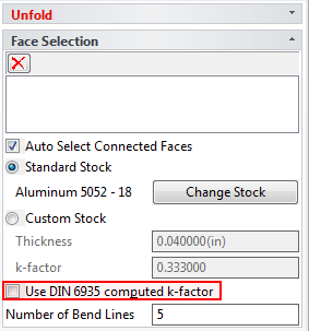
Unfold Solid/Surface Din Standard Setting
Structure Part Plane AutoFit
When using Structured Parts, datum planes on the part are displayed to allow the reference associations to these plane locations. Improvements have been made to automatically update and size the datum planes when the geometry is modified. This capability allows for better selection and visualization of the planes when the geometry is actively changing through the design process.
Automatically Enable Direct Face Move editing on Face by TriBall
Improving the design flow, users can now directly invoke the move face operation by selecting a face and enabling the TriBall which is used in the operation to reposition the faces location. This new behavior reduces the need to locate the Move Command when the user is in the process of selecting and modifying the face information.
Improved Support for Large Imported Data
It is common to work with imported data from other applications during the design process. Improved and new options have been added to the Import options to improve the application performance and users access to structural information. Users have clear settings on defining data to be used as reference and to maintain the assembly structure during the combine as reference operations.
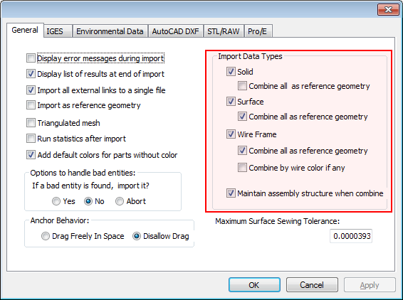
Import Dialog Options Page
Directional Based Surface UI Indicators
For Surface commands such as Loft and Ruled surfaces, new indicators have been added to the selected curves that denote the curve direction. In addition, users can directly select on these indicators to toggle the direction reducing the need to right-click edit (or re-picking the curves).
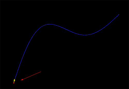
Surface Direction UI Handle Toggle/Indicator
General Improvements
Application Memory Usage Improvements
Improvements have been performed throughout the application to improve the memory management. The most notable improvements have been made in the management of the graphical representation in the 3D. These improvements reduce the memory overhead of the application yielding better performance and reduces requirements on increased hardware demands. In addition, improved stability in the application is achieved by reducing issues caused by memory limits.
Large File Loading Performance Improvements
Focus has continued in the area of loading files and these recent improvements have yielded results near a 20% reduction in loading larger assembly sets. Each release, our team has dedicated resources to continue improvements of the loading of files. This release has included significant gains that will be noticeable when working with large assemblies..
Interaction Improvements
Improvements have been implemented to improve the applications interaction and responsiveness in areas of the sketch environment (especially in selection) and when toggling between environments within the application (such as switching windows between the scene and drawing environments).
Start-up and Document Switching Improvements
Continuing our improvements started in our last product update, changes have been implemented to improve the application start-up. This includes embedded environment start-ups such as the DRAFT environment.
2D Projected View Creation Improvements
New thread support has been added in the DRAFT environment when creating projected view layouts. This added support improves the overall view creation performance especially when dealing with larger assembly files and while working on multiple thread supported machines (such as multiple core machines).
2D DRAFT Improvements
Section Line Repositioning Handle Support
New handles have been added to the section lines in DRAFT to enable repositioning. The section lines can dragged and snapped to other elements using the standard snap options. In addition, the section line labels can be repositioned to accommodate changes after updates.
Modify (Add/Delete) Section Label Support
Section line labels can now be edited to add or delete labels after the initial creation. Selecting the Modify Dimension command and selecting the label, options will be presented to allow the editing.
Improved Connected Dimension Support
Improvements have been made on the dimensional associations to the 3D geometry projected in to the 2D drawing views. For example: Dimensions related to edges in sectional views are maintained during updates performed on the 3D geometry.
Simplified Merge Linked Part BOM Settings
When creating a BOM, it is common to have linked parts merged and counted as a added quantity. Improvements have been made to enable this setting during the BOM creation instead of the BOM editing mode reducing extra steps previously taken to enable this capability.
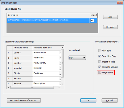
BOM Merge Link Files to Quantity
Item Bubble Display Shape Setting
New capabilities have been set to allow the global and individual setting of the item bubble display. During the "Fill in BOM" command, a new option has been added to allow the ability to set all the item bubbles display globally to a different frame shape. To individually set the item bubble frame, simply right-click on the item bubble and enter the property option to specify the frame display.
Additional Target Dimension Types Added
New dimension types have been added in the drop-down menu for "Dimension" to allow for specific types such as Linear, Angular, Aligned, Diameter, Radius, and Arc Length. Enabling these options allows the user to place multiple dimension of the same type in a single command.
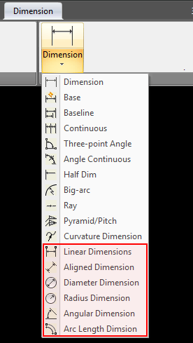
Additional Dimension Types Added to Dimension Command
BOM Template Automatic Weight Calculation Support
During creation of the BOM, a new option has been added to the creation dialog to enable the calculation of the weight. With this option enabled, the calculation will be made automatically and will display in the resulting BOM table. Location and settings to calculate the BOM can be configured in the "Fill in BOM" option.
Infinite Line (xline) Additional Input Creation Types
New creation types for the infinite line have been added to support two point, horizontal, vertical, bisect, angle, and offset. This improves the ability to create the infinite lines in the desired location and orientation.
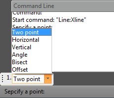
Xline Additional Creation Types
Create New Block on Copy/Insert
During Copy/Insert of a block, an option has been added to create a new block as the result. This option will prompt the user to input the new name for the copied/inserted block and then will continue with the normal placement of the block. This new functionality increases the ability to reuse existing design data.
Support for Hide by Block
When using blocks in the design environment, new options have been added to hide geometry behind blocks. Simply select the desired block and right-click select "Hide" to hide all object behind the selected block geometry.
Quick Trim By External Linked File Support Added
When using external linked files, new capabilities have been added to the Quick Trim command to enable trimming by the referencing the external linked files geometry as the trimming to element.
Divided Hatch by Geometry Capability
Hatch geometry created can now be divided by intersecting geometry that crosses the hatch boundary. Each individual hatch boundary created can be independently controlled for display settings.
Find/Replace Text in Block Support
The Find and Replace Text command has been improved to support searching and replacing text within Blocks as well as the current drawing. The Find and Replace text command can be enabled in the Menu under Modify.
Quick Select Setting in Property Browser
A new option has been added on the Property Browser to enable selection in the document based on user defined criteria. For example: Users can enable selection by a specified layer to select all geometry elements using the layer type. This option has been added in a convenient location to provide a better method of selecting element throughout the drawing.
Object Snap Toolbar Available
Object Snaps are commonly used in the DRAFT environment for various commands. Many of these option are accessible by hitting the spacebar during commands such as dimensioning. However to improve efficiency and reduction in the learning curve, a new toolbar has been added with these available snap types. Once enabled, users can select the desired snap type and then select on the geometry element to invoke the snapping behavior.
![]()
QuickSnap Toolbar
Easy Access to Print from Model/Layout Tabs
A new right-click option has been added to the Model/Layout tabs to directly invoke the Print command for the selected tab.
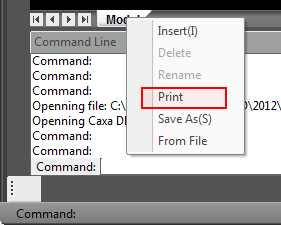
Print Option on Right-Click of Model/Layout Tab
Operating System and System Updates
Advanced OpenGL/Direct 3D Upgrade Improvements
Upgrades to the underlining graphical engine in the IRONCAD Advanced OpenGL/Direct 3D have been performed. HOOPS 3D from TechSoft3D has been updated to the latest version 19.04 which improves real-time graphical performance and visual quality. For details on improvements in the HOOPS engine, visit http://developer.techsoft3d.com.
Subsystem Upgrades
o Parasolid™ Modeling Kernel Updates - Updates to the Parasolid kernel have been implemented. These updates include various improvements to the modeling geometry as well as support for new versions. Files up to version 24 can be imported and exported.
o ACIS™ Modeling Kernel Updates - Updates to the ACIS kernel have be implemented. These updates include various improvements to the modeling geometry. The current version support is version 21 SP3
o TechSoft 3D HOOPS™ Toolkit Updates - Updates to the latest version of the HOOPS toolkit allows users to export and share IRONCAD scene files in the latest HSF format. This allows users to share data with other applications such as a viewer while taking advantage of the latest visual and performance improvements.
o Spatial 3D Interop™ Translators - Many import/export options available in IRONCAD (including IGES and STEP) have been updated to the latest versions offered from Spatial's InterOp version 22. This update improves the reliability of the import/export interoperability between CAD systems. In addition, the Native Translator versions supported in the Translator Bundle have been updated to support the following new versions: Inventor 2012, Wildfire 5.0, SolidWorks 2011, Unigraphics NX versions 11 to 18 and version NX1, NX2, NX3, NX4, NX5, NX6, and NX7.5, and CATIA V5 supports Read versions R2 through R20 and Write versions R6 through R20.
o 3D PDF Upgrade - The IronCAD Design Collaboration Suite Products support for 3D PDF has been upgrade in this release to use libraries from TechSoft3D based on the PRC format. This upgrade improves the overall stability, quality, and performance of the generation of 3D PDF from the IronCAD DCS products.
New and Updated 3rd Party Applications
NEi Software, Inc. – “NEi Nastran for IronCAD” - Nastran Based FEA in IronCAD's 3D Associative Environment
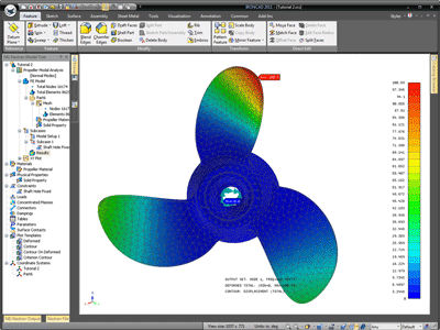 NEi Software and IronCAD have teamed up to bring the Nastran Based FEA to the IronCAD Design Collaboration Suite products IRONCAD and INOVATE. "NEi Nastran for IronCAD" is a powerful finite element analysis solution designed to run inside of the user interface of IRONCAD and INOVATE. Users will be able to use the standard IRONCAD and INOVATE product functionality to design products and then performed analysis simulations directly within the application eliminating the need to launch any additional standalone applications.
IronCAD registered users will be able to download and install the “NEi Nastran for IronCAD” that will enable users to run and explore the following capabilities as a fully functional node-limited version within IRONCAD and INOVATE:
o Linear Static and Steady-State Heat Transfer
o Normal Modes, Buckling, Composites, and Prestress
o Advanced Dynamics (Transient Response, Frequency Response)
o Nonlinear Analysis (Nonlinear Static and Transient Response)
o Nonlinear Transient Heat Transfer (Static and Transient)
Options are available to purchase licensed versions of the functionality to meet your design needs. For purchasing options, please contact at 1-800-339-7304 (sales@ironcad.com) or your local reseller (http://www.ironcad.com/research/locatereseller/).
NEi Software Customer References:
Georgian Aerospace Group
 "When we started looking for an FEM package, we considered over 17 programs and selected NEi Nastran. I cannot emphasize enough how important the support of the people at NEi Software was in our decision. Sales people can offer anything, but the proof is after you purchase, how is the support. The people at NEi Software lived up to all their promises. I was a neophyte FEM analyst and during my first few projects I had many questions. NEi Software handled them all. This has allowed me to complete my projects on time. I never expected to get the type of support we have because of the affordability of the NEi Nastran solution." Joel Simansky Senior Engineer
L’Garde
 "The timely and technically sound support we are getting from NEi Software does not even come close to the kind of support we DON’T get from two other FEA Companies we have a licenses with. NEi Nastran is more accurate compared with the two other commercial FEM packages we have. To say that we at L’Garde are very pleased with your support will be an understatement. I just wish that we would have known about you sooner." Dr. Art Palisoc Program Manager
