|
Design Collaboration Suite 2013
|
|
|
New Features Introduced in the IronCAD Design Collaboration Suite 2013 "Next Generation" |
|
|
Quick Links
Productivity Focused Improvements
Operating System and System Updates
The revolutionary IronCAD Design Collaboration Suite 2013 "Next Generation" is truly the most productive design tool in the industry today. The 2013 release focuses on improving the existing capabilities to streamline the process, which increases the overall productivity for designers and engineers. Users will immediately feel the impact of the overall mouse-click reduction and mouse navigation enhancements. Furthermore, these streamlined processes bring additional flexibility and capabilities to the design process, breaking tedious tasks down to simple operations.
In addition to the general productivity improvements, the development team focused on achieving greater customer satisfaction through continuous improvements of stability, quality, and performance of the application. This release includes numerous enhancements to the quality of the application and performance of the application.
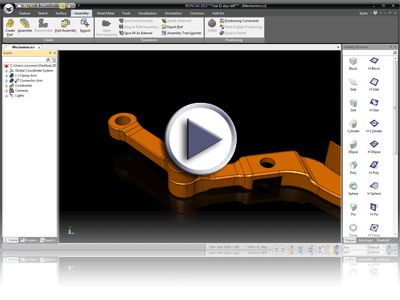
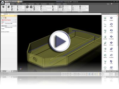
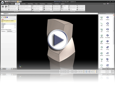
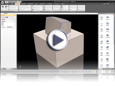
Please refer to the information below to find details and videos of the major improvements included in the 2013 release.
Productivity Focused Improvements
Associative Reference for Pro/E and UG/NX
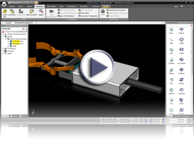
Design collaboration often involves sharing data with other applications to complete the overall design. Using the Translator Bundles, users can reuse native formats such as Pro/E (Creo), CATIA, UG/NX, SolidWorks, and Inventor. The 2013 release has further extended the compatibility for Pro/E and UG/NX files by creating an associative reference to the imported data. For example, users can import a Pro/E file and then use it in the design environment where references can be created (constraints or positional dimensions), modified, associated to drawings with annotations, and applied in other operations like coloring. If the original Pro/E file is modified by the source application, users can simply right-click on the imported data in the IronCAD applications and select "Update" to incorporate these changes into the design. All of the references that were previously created will be maintained and updated. This enhancement improves collaborations with these formats, allowing users to work more effectively in the 3D environment as well as in the 2D mechanical environment to modify details while maintaining associations with the corresponding data.
Faster Methods to Complete Commands Using Middle Mouse
During the design process, users often initiate commands that require them to accept or cancel.. Normally the option to confirm a command is found in the property browser. This, however, would require users to change their focus from editing the geometry in the scene to completing the command through accessing the property browser or the resulting menu from a right-click. This process may be repeated many times during the design process and can affect the overall design productivity. To improve this process, users can now simply click and release on the middle mouse button to accept the command action or shift and click the middle mouse button to cancel the command. This capability allows users to maintain focus on the geometry editing area which would effectively reduce mouse travel time, hence improving the design process.
Scene Browser Quick Search
Assembly designs often result in a complex tree structure that is difficult to find the desired parts or assemblies. The scene browser now supports a Quick Search Filter that grants users with the ability to input the name of a desired part/assembly and search for it. The resulting scene browser will be filtered to display what it has found. Users can quickly find their desired elements for the design task without having to traverse through the complex tree structure or to use the more advance search functions.
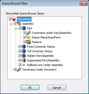
Scene Browser Filter Display Modes
Often user are either working in a part design state or an assembly design state. In each mode, different levels of access and information display may be desired. Users can now configure the scene browser to assist in these design modes. For Part Design, the scene browser will be able to display more information such as detailed features. Assembly Design, on the other hand, will reduce the information that is displayed in the scene browser by hiding features that is not required at this state. In addition, users can select a custom filter to set the desired display information in the scene browser for their particular design needs. Overall, these filters can reduce the time spent navigating the scene browser and speed up the design process.
Tabular Documents
Users typically have multiple scenes and drawings opened simultaneously. Currently, toggling between these documents takes quite some time to complete. Users now have the ability to turn on tabular display that shows all open documents below the Ribbon Bar. They can quickly toggle between open documents and easily determine which of them are open using this new setting which is configured in the customization menu.
Direct Input Fields support for Mathematical Input
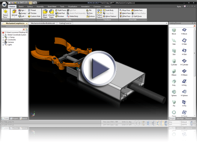
Improvements have been made to the direct input fields on the IntelliShape handles and TriBall handles to give users the ability to input mathematical formula. Now, there is a button for users to toggle between the two input types on the direct input fields. By default, the system will only accept numeric input. Once the button is toggled, users can input mathematical expressions such as +,-,/,*,sin, cos, etc. to aid in sizing and positioning. This toggled state can be set as the default input method based on users’ preference.
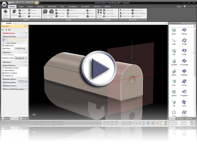
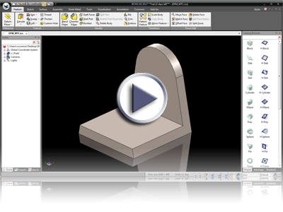
Extrude Feature Support for Remove Material Side (inside/outside)
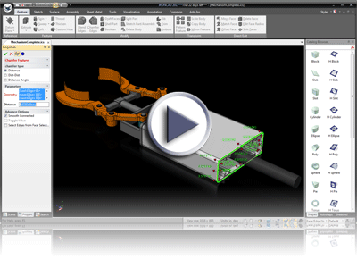
It's common to face the task where a user may have a solid piece of complex geometry that they wish to modify by removing everything except what is defined by a closed sketch outline. Normally, this process would require the user to create the intended closed profile followed by another closed profile around this outline to remove all of the geometry in-between. To improve this process, a new Outside Cut option has been added to the Extrude Feature command which is available under the Remove Material operation. This allows users the ability to simply draw a closed profile and select the option to remove all material outside of the 2D sketch automatically without any additional steps.
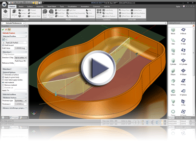
Extrude Feature Support Single Line and Thickness
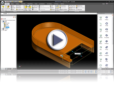
A new option has been added to the extrude command to create 3D shapes from non-closed profile, or rather a collection of lines, in the sketch and input a thickness and direction to create the solid extruded material. This capability allows users to draw profiles along a centerline path and simply provide a thickness to the material instead of using offset commands to achieve a similar result.
Camera Smooth Zoom/Rotate
When working in 3D and performing camera movements like rotations and alignments, it can be difficult to understand the orientation of the model. A new behavior has been added to the camera commands to perform a smooth transition. For example, using the Look At command, the model will smoothly transition to the new alignment allowing users to understand how the model have rotated to achieve the orientation. Similarly, the camera would smoothly orient itself to look along the Z-direction of the sketch plane when entering into the sketch mode. This will allow users to understand the orientation of the model as it transitions into this alignment.
Import Placement Options (User Place)
When importing geometry into the 3D scene, it may be desired to be able to directly position the geometry during the import instead of placing it at the default location. Enabling this new option, the geometry will be placed on the cursor for users to drag and position before placing it at the cursor’s location or snapping it to existing geometry. This feature is similar to the Drag & Drop actions from the Catalogs. This reduces extra clicks from selecting the geometry and enabling positioning tools after an import.
Show Selected and Sub Items
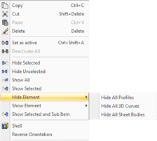
When working in an assembly environment, it is common to hide parts and assemblies from view in order to inspect a specific area clearly. This capability is useful, but it often takes additional effort to selective and show each hidden components. A new option has been incorporated to show the selected hidden element and all that is under its tree structure such that it speeds up the capability of working with hidden components (For example: Show the Assembly and all the hidden parts below this Assembly).
Show/Hide Elements (Profiles, 3D Curves, Surfaces) in Structured Parts
Structured parts usually contain building blocks of multiple feature types such as 3D Curves, 2D Profiles, and surfaces. These building blocks can remain visible or can be turned on to access these elements in later commands. When the feature tree grows, it may become difficult to visually see the geometry in the scene due to these building elements. Users can now show/hide these elements independent of the traditional show/hide commands to make it easier to navigate and work with these structured parts.
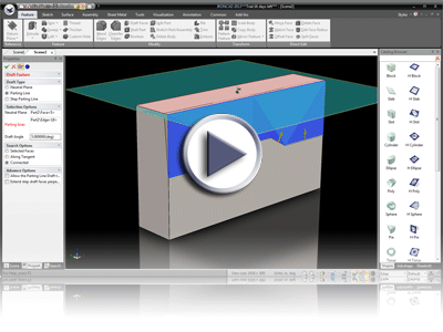
Parting Line Draft Direction Alignment to Pull Direction by Default
Improving the functionality of the draft command and the parting line draft, the parting line direction will now follow the pull direction by default which reduces the number of clicks to perform this command. In majority of the cases, the pull direction would be the desired direction for the parting lines and the new behavior make the selection of multiple line segments much easier with less clicks to alter the parting line direction.
Advanced Curve Selection Tools
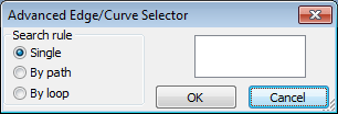
In some commands, the selection of curves are important. The patch surface, extract curve, and merge curve command now have an option to select the loop of a curve (even if it is not smoothly connected) by selecting “A” in the selection dialog. Additional options are available to handle multiple branches on a curve. For Example, a user can select a loop of curves by selecting one of the curves along with a face that the remaining curves reside on.
General Improvements
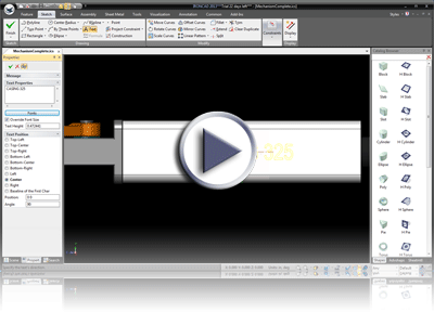
2D Text in Sketch
The 2D Sketch now supports the ability to insert 2D Text into the sketching environment. Users can enter text of desired font size and height, and place it in a preferential location within the sketch. This command is useful for applying removal type operations, for example recessing text into a part.
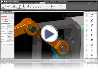
Measurement Command improvements
The Measurement Command has been improved by changing the default behavior to minimal distance, providing users with the most common action used. In addition, an option has been added to quickly measure the diameter of circular geometry. To aid in better visualization, options have been added to denote the direction of the measurement as well as the ability to hide previous measurements for clarity concerns..
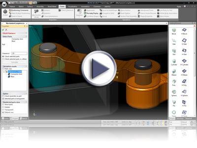
Clearance Check
A new command, in addition to the interference check, has been added to check clearances. Users now have the ability to check the distance between parts by a minimal clearance distance. The user interface will numerically display the distance to help inform the user of the current clearances.
3D Section support for Structure Parts (Graphical Section)
The 3D Graphical section (non-precise) is now supported in Structured Parts to aid in design visibility when needing to work inside of geometry.
Constraint Status Display in Scene Browser
Parts and Assemblies will now display the over, under, or fully defined constraint status in the scene browser. This option allows users to get a quick status update of the parts and assemblies in the scene for a better understanding of their positioning and movement behavior when changes to geometry or mechanism movement are performed. Note: This option can be disabled if not needed.
Large Toolbar Icon Support
Toolbar Icons now have full support for the Large Icon display to better aid in the visibility of the user interface when monitor resolution is of concern.
2D Sketch Performance Improvements
General improvements have been implemented for better performance in the 2D Sketch when dealing with larger data sets. Actions such as selection, highlight, and camera interaction have been improved in the condition of larger data sets.
Support for DFM Offset, Delete Face, and match in Structured Parts
The Direct Face Modeling operations for Structured parts have been enhanced to support offset, delete, and match face operation. This additional support extends the flexibility for users to make changes to geometry late in the design process when it may be difficult to change the structured order of the design.
Sew Command to Convert Closed Surfaces to Solids
Ability to select multiple surfaces that make up a closed body and convert it to a solid geometry. This command is useful when importing geometry that results in many surface shapes. Users can patch open areas and use the sew command to stitch the surfaces back into a solid.
Solidify Command
Ability to select a set of solids and closed curves to combine into a single solid shape. This command is an extension of the sew command as it can sew and Boolean both solids and surfaces together in a single operation.
Performance improvements in Structure Part Regeneration
General improvements have been made to improve the regeneration speed of structured parts that have many feature dependencies. This reduces the overall design time when making modifications to complex parts.
Save File Performance Improvements
General performance improvements have been implemented for the save command to reduce overall design time.
Healing Options on Import (Perform Heal on Import)
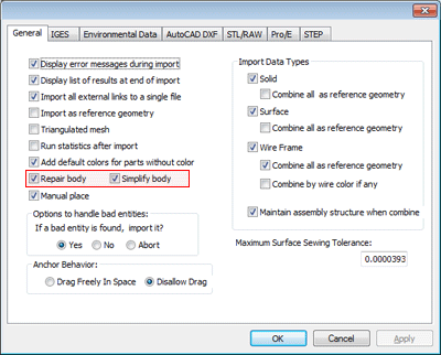
During import, options can be enabled to automatically perform the healing command to help stitch gaps in imported surface data. This reduces the need to perform surface operations at a later stage to close gaps in surfaces/solids.
Direct Face Modification Maintain Tangent Control on Moving Faces
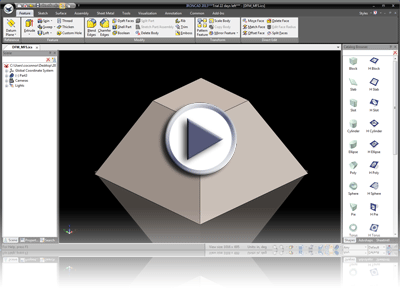
A new option has been added to allow the ability to move a face while maintaining tangency connections that results in alterations of connected faces. For example, take a block with an arc on the top. Moving the side of the block will adjust the size of the arc to maintain the tangency. Similarly, if the user alters the radius, the sides of the block should adjust accordingly to satisfy the changes. This option extends the capabilities of editing imported data or designs late in the design cycle.
Direct Face Modification Maintain Face Size on Move
New options are available to move a face while maintaining the size of the current selected face. This results in the connected geometry to alter to satisfy the applied movement while fulfilling the size restriction on that face. This option is useful when making a modification to an element where the modified face needs to maintain the current size but may need to be repositioned. This option allows connected geometry to automatically adjust to satisfy the modification.
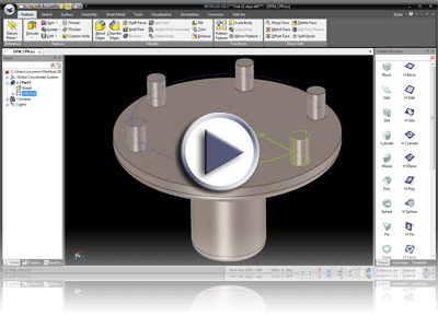
Direct Face Modification Support for Circular Pattern Recognition
When applied on imported data, the feature recognition command will automatically detect circular patterns and create the respective feature to allow for modification. This allows for better modification of imported data to maintain logical patterns in geometry.
Sheet Metal Unfold of Overlap Support
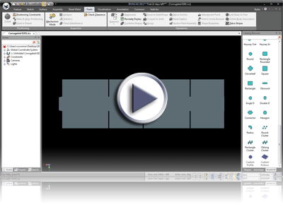
The unfold operation has been improved to detect and handle overlapping bends so that the tool can properly unfold the sheet metal. This is useful in shapes such as corrugated boxes that have overlapping flaps. Note: Bends must use the automatic constraint options and must maintain the bend/stock order in the scene browser.
Sheet Metal Unfold Bend Segment
New options to unfold individual bend segments have been added. This allows users to build different configurable stages of the unfold for documentation and manufacturing instructions that can be referenced to in the detailing process (IntelliShape level configurations).Note: Bends must use the automatic constraint options and must maintain the bend/stock order in the scene browser.
Sketch Edit Constraint Dimension Command
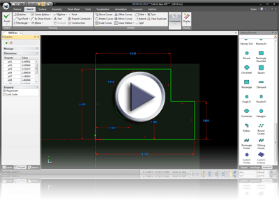
A new option in the sketch has been added to edit all dimensional constraints in a dialog. This allows the ability to see all of the dimensions and apply values before updating the geometry or making use of the parameter table. Overall, this reduces the effort to change multiple dimensions without the need to get into more complex operations.
Extrude to Body Support in Structure Parts
Extending the design capabilities when working with Structured Parts and multiple bodies, a new behavior in the Extrude command has been added to extrude to geometry on other bodies. This is useful when the bodies may be used as different parts where the extrude of one part can update based on the position of a second body/part.
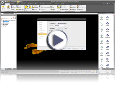
Assembly support for Material Properties
When working with imported or referenced data in a design, in many cases, it may not be necessary to display all the part and assembly information in the detailing process, including the bill of materials. For these cases, assemblies can be set to treat as a single part so that the entire assembly will only appear as one entry in the BOM.. Also in this case, material properties can be set to properly denote the material for this type of assembly so that it can properly call out material specifications and weight.
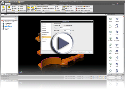
Link Options for Material Properties
In some cases, similar parts may have different material properties. When working with linked parts, the Material Properties have added the "Only this instance" or "All linked instances" option to allow for different linked parts to have different material properties.
Tools/Options Dialog Update
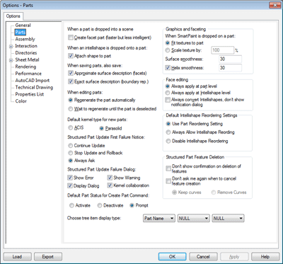
The tools/options page has been updated and rearranged to clarify categories and make additional options easier to locate and configure.
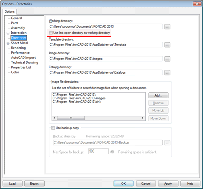
File Open Last Path Setting
An option has been added to automatically set the last open path location as the working directory. It is useful to automatically set the path for future opens/saves using the Last Path Setting if you work in different directories.
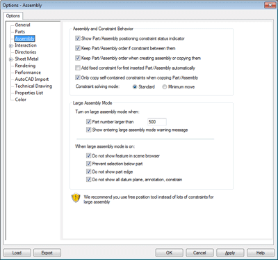
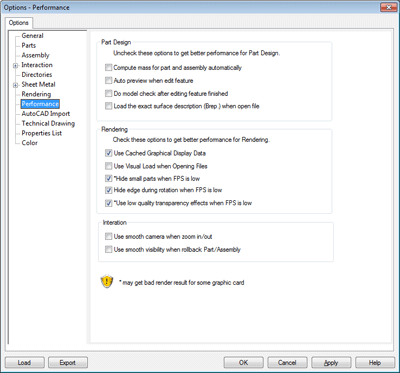
Performance and Assembly Settings
In the Tools/Options, there are new settings for "Performance" and "Assembly" that are used to change display settings based on the data presented in the scene. This can improve overall performance when working with larger assembly files.
2D DRAFT Improvements
Detail view Association
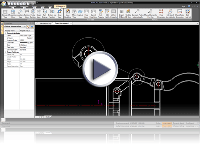
Detail views in DRAFT have been updated to maintain association to the views. Moving the views in the drawing will properly update the detail views reducing extra effort to manually update these views after changes are performed.
Hole Callout Tool
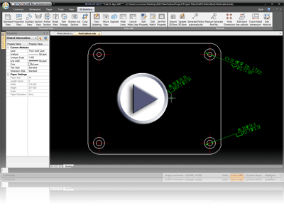
A Hole Callout tool has been added to allow users to pick on holes to properly callout information such as depth, counterbored, countersink, etc. This option reduces effort in transferring callout information and allows users the ability to label non-custom holes with standard information like the depth and diameter.
Edit Detail View Support
Detail views can now be edited to change the size and location of the detail to properly handle design modifications. When these changes are performed to the detail region, the resulting detail view will update based on the changes automatically.
Edit Break View Support
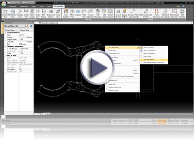
Break Views can now be edited to adjust the location, type, and break size. Right-clicking on the view and editing the view properties will provide these options to edit its break view if there is one that is associated.
Hole Table Origin Definition and Association for Update
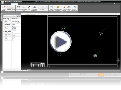
The Hole Table (Auto-Hole List) command has been improved for users to set the reference origin for hole labeling. This change of setting will remain associative to the model such that the table automatically updates respectively. In addition, editing options have been added to allow the ability to edit holes (add/remove) after the initial creation of the hole table.
Hole Table Support for Callouts
The Auto-Hole List (Hole Table) now supports Hole Callout information such as depth and hole-type information. When selecting custom holes that have thread information, the information will automatically appear in a column of the hole table.
Shaded View Support
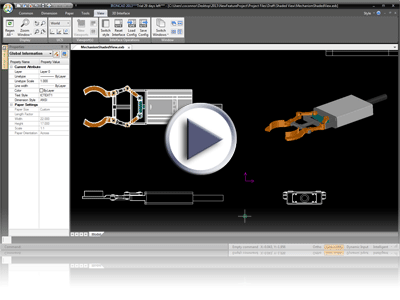
New support has been added in DRAFT to create quick views as shaded in the DRAFT environment. These views can be "shaded" and "shaded with hidden lines" to better illustrate models in the 2D detailing process.
Configuration BOM Support
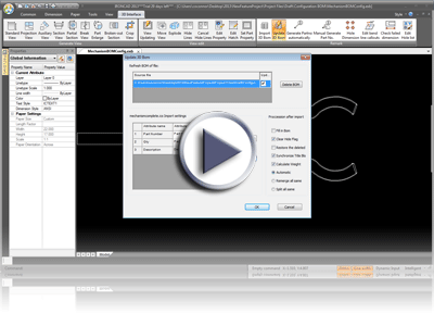
DRAFT BOM has been improved to support the ability to define configuration based BOM’s similar to that of ICD’s. This allows the ability to create views based on configurations followed by a Bill of Material that can properly callout this view.
Individual View Configuration Support
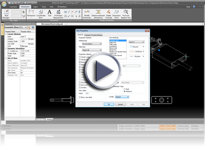
Standard views are now configuration based views during creation or editing. Each view can be edited and configured to show/hide elements or even to show different positional locations.
Sheet Metal Bendline Callout Support
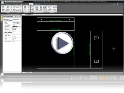
Sheet metal bend lines can now display callout information (Bend Directions, Bend Radius, Bend Angle) in DRAFT with options for placement location. Callouts can be set to show desired information, and users can control the placement of the bend callout as either above/below the line or as a text with leader.
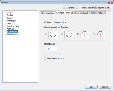
Cosmetic Thread ISO Style Support
Cosmetic Thread Display setting has been improved to allow for ISO style support in the DRAFT environment. Settings are implemented to control the cosmetic thread callout either as a closed circle or as a 270 degree non-closed circle. In addition, the location can be adjusted as well as the thread run-out.
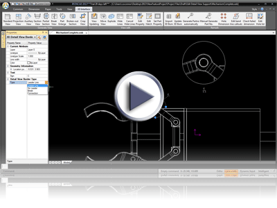
Detail View Style Support (Broken Circle, Lead/No Lead Line, Connected Line)
Detail views have been enhanced in DRAFT to support different standard types such as Broken Circle display, Leader Lines, and connected line display. Previous versions only supported connected line detail views.
Export BOM on 64-bit to Excel
BOM table contents can now be exported to Excel files from 64-bit machines to allow for the reuse of data in other applications.
Simplified Chamfer Options
Simplified display has been added for chamfers that provide additional standard options on detail drawings. Chamfers have a simplified display style for 45 degree chamfers.
Section View ISO Support and Pick Curve Options
The Styles for the section views have been updated to correctly reflect ISO/ANSI standards, and a new option to pick an existing curve to define the section line has been added to improve speed and clarity of the section command.
Automatic Item Bubble Improvements (No Overlap, Alignment)
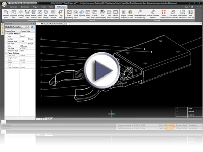
New options for the Automatic Item Bubble command have been added to support the alignment location and to prevent overlapping leader lines on the Item Bubbles. This reduces time spent creating item bubbles and arranging them to properly fit. Users can choose whether to place the alignment on all sides of a view or just on specific sides. When placing the item bubbles, the leader lines will automatically adjust to avoid overlaps as the cursor is moved to define the location.
Broken Out Section View Depth Selection
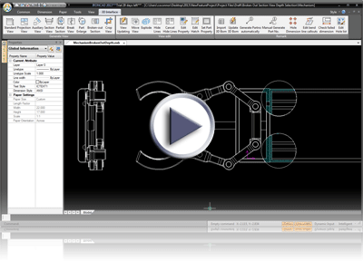
New options have been added to define the broken-out section view depth by inputing an exact distance in the DRAFT environment. This allows for accurate placement of the broken-out section view depth by giving users the ability to pick on locations in other views that defines the exact depth.
Item Bubble Manual Creation Option to Follow BOM or Reorder
When placing the item bubble manually, users now have the option to have the item bubble numbering follow the currently defined BOM order or to define the BOM order as they select the geometry. This improves the flexibility in getting the desired results for the BOM.
Disassociated Dimension Display
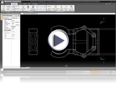
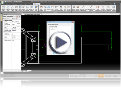
New options have been added to display and clean-up dimensions that have been disconnected from the 3D Geometry due to lost geometry for example. User can visually see the disassociated dimensions in a list and can denote them to have a different color on the drawing. In addition, these dimensions can be easily deleted in a single operation within the display.
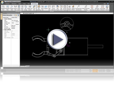
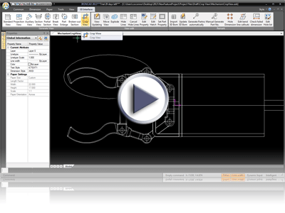
Crop View Support
Crop views have been added to DRAFT to crop out unnecessary information from a drawing view. Crop views are define by 2D Geometry creation tools. Users can create and remove the crop regions to show/hide areas of interest.
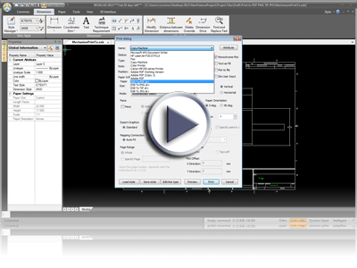
Print to PDF, PNG, TIF, JPG
New drivers have been added to DRAFT to support printing to PDF, PNG, TIF, and JPG instead of using 3rd party drivers to achieve similar results. This provides the users the ability to export the drawing details to visual formats for sharing and collaborating outside of the design group.
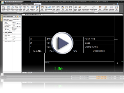
BOM Support for Treat as Part for Assembly
The DRAFT BOM has been updated to properly support the Treat as Part options used on Assemblies in the 3D environment. This allows users to reduce BOM data that may not be needed. For example, users may insert assembly data from suppliers and only need to callout the information of the Assembly but not the parts below. Setting the assembly to Treat as a Part will prevent the parts from being included in the BOM.
Operating System and System Updates
Subsystem Upgrades
o Spatial 3D Interop™ Translators - Many import/export options available in IronCAD Design Collaboration Suite (including IGES and STEP) have been updated to the latest versions offered from Spatial's InterOp version 23. This update improves the reliability of the import/export interoperability between CAD systems. In addition, the Native Translator versions supported in the Translator Bundle have been updated to support the following new versions: Inventor 2012, Creo 2.0, SolidWorks 2012, Unigraphics NX versions 11 to 18 and version NX1, NX2, NX3, NX4, NX5, NX6, NX 7.5 and NX8, and CATIA V5 supports Read versions R2 through R22 and Write versions R6 through R22.
New and Updated 3rd Party Applications
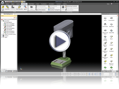
SketchUp Integration
New support for Sketchup .SKP files has been added to the IronCAD Design Collaboration Suite applications. User can access Sketchup files they created or access the vast user community models located in such places as the Google/Trimble 3D Warehouse. Users can import these models that will import as graphical representations that can be used to populate designs. Users will be able to position, apply SmartPaints, and reference edges/faces of the imported models.
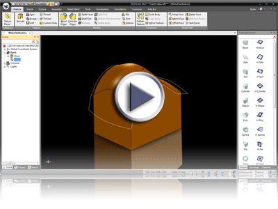
Rhino Pluging Updated
The IronCAD-Rhino Integration has been updated to work with both the latest verison of IRONCAD and Rhino 4. The IronCAD-Rhino Integration provides users with a seamless way to harness the power of both IronCAD and Rhino in the design process. By using Rhino for styling and IRONCAD\INOVATE for mechanical features, you will experience dramatic productivity improvements over using each product alone.
Key Benefits
-
Data Compatibility - Ability to import Rhino .3DM files into IRONCAD or INOVATE for further design work in solids.
-
Increased Productivity - Use IRONCAD and Rhino together to achieve designs not easily done with either software individually. The combination of IRONCAD and Rhino creates a true synergistic modeling solution. By using Rhino for styling and IRONCAD for mechanical features, the user will experience dramatic productivity improvements over using each product alone.
-
Extending Rhino Capabilities - Provide Rhino users with the detail design and 2D drafting capabilities of IRONCAD.
-
Shell a Part/Model - Shelling of solids provides a quick and simple alternative to the offsetting of surfaces. It provides predictable and stable results that can be edited as needed.
-
Create Ribs, Bosses, and other Mechanical Details - IRONCAD's award winning catalog-based design tools allows design features to be dragged and dropped onto a model and easily positioned or resized using simple to use handles.
-
Powerful Positioning Tools - Position features, parts and assemblies easier than you ever thought possible using tools found only in IRONCAD such as SmartSnap, TriBall, SmartDimensions, dynamic mate and align.
-
Simplified Feature Editing - IRONCAD supports a full feature tree popular in today's leading MCAD systems. It allows quick access and individual editing of each feature. Unique to IRONCAD is its ability to edit any feature relative to any other feature/part/assembly even it if occurs later in the tree structure.
-
Animate and Visualize the Model - Full time dynamic shading dramatically improves the user interaction during the modeling process. Pre-created animations can be dragged and dropped from a catalog directly onto the model to simulate product motion.
-
2D Detail Drafting - Using IRONCAD, users can use the finalized design to create full detailed production drawings to communicate to downstream production processes.
Sample uses of the IronCAD/Rhino Integration
-
Import - Start a conceptual design in Rhino using complex surfacing, then import the geometry to IRONCAD and finish the mechanical design in solids.
-
Design Iterations - Use the IRONCAD/Rhino Integration to make design iterations between the two programs while working on the same geometry. This can be helpful when you need to develop styling and mechanical features at the same time.
-
Stylize a Design - Use the IRONCAD/Rhino Integration to stylize a finished part that was created in IRONCAD.
-
Production Detailing - Take the stylized design from Rhino then bring it into IRONCAD to create the detailed drafting drawings required by manufacturing.

