|
|
New Features Introduced in IronCAD Version 11.0 |
|


|
|
Quick Links
Assembly Management Improvements
Detailed Part Design Improvements
2D Technical Drawing Improvements
Operating System and System Updates
Assembly Management Improvements
Windows 64-Bit Operating System Support for large Assembly Data
Customers in IRONCAD are continually expanding their needs for large assembly data. This can sometime push the limits of a 32-Bit operating system that has limited amount of available RAM and often performs memory swapping with virtual memory. To aid the customers, IRONCAD V11 has added support for the 64-bit operating system to allow the users to take full advantage of the systems capability.
New Loading Capability to Reduce Memory and Improved Save Times
New loading capabilities have been added to IRONCAD to improve the memory management and load/save times on large assembly data. During the open of files in the Advanced OpenGL/Direct3D rendering mode, only the structure and feature information will be loaded along with the light weight graphical information. When the users modify the features or when certain commands need this information, the data will be automatically loaded for the edited components and any related components. The capability improves the following areas:
Save - Saving files have approximate improvements of a 10-30% reduction in time. This can help reduce the overall design time by spending less time in the system generated overhead time.
Memory Management - The memory allocated has been reduced by 10-15%. This again saves design time by lowering the chance of virtual memory swapping to occur.
Interaction - Interaction within the large assembly models will be improved due to the lighter load, since memory and internal data is only loaded for the necessary components being worked on in the design.
Interaction improvements
Many changes to the internal environment of IRONCAD have been performed to improve the interaction of data when large assembly data is loaded. Selection, edit of geometry, drag and drop of new geometry, and TriBall positional changes have all been improved to interact consistently fast both when the Scene Browser structure data is visible or closed.
2D Technical Drawing Performance Improvements
Improvements have been made in the 2D Technical Drawing environment to enhance performance in the view creation process. View creation with the "Automatic creation of center lines/marks" and the "Select Part/Assembly within the Scene" enabled have been significantly improved.
Sketch Improvements Containing Large Data
Sketches containing large data of curves and grids have been improved in the Advanced OpenGL/Direct3D rendering mode when camera operations are performed. Noticeable improvements are seen in the general camera interactions at both the full zoomed level as well as the zoomed in level when data is clipped to perform faster.
Zoom to Selection
Common interaction commands when dealing with large assembly data have been added to lower the overall design time spent in IRONCAD. One such improvement is the Zoom to Selection. The option can be selected in the Scene Browser or from the graphical display area to quickly zoom to the component being worked on. This command can apply to assemblies, parts, and even features. Combining this option with other IRONCAD utilities like the Hide Command, can improved time navigating the display to find critical components.
Zoom to Selection Example
Find in Scene Browser Command
Another common interaction command for large assemblies, the Find in Scene Browser, helps reduce design time spent navigating the structure to find the selected components. This new command automatically directs you to the selected object in the scene browser which will expand to the correct level to allow the user direct access to the item.
Find in Scene Browser Example
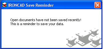
Save Notification Reminder
When dealing with large assemblies or even smaller files, many time users forget to save data along the way. A new automatic save notification has been added that can be set to a user defined time interval to help remind the user to save and store their critical design data.
Assembly Calculated and Specified Mass Settings
Assemblies can now carry calculated and specified mass values that can be transferred to the Bill of Materials on the drawing. The calculated mass is a calculation of the total mass of all parts included in the assembly. Specified mass allows the user the ability to specify a set mass for the assembly. This setting is useful for imported data that you may want to use in your calculations. The mass settings are found in the assembly properties and the specified mass can also be set in the property browser of the assembly.
Assembly Mass Calculation Example
User Interaction Improvements
Advanced Scene Browser Search Capability
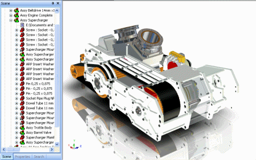
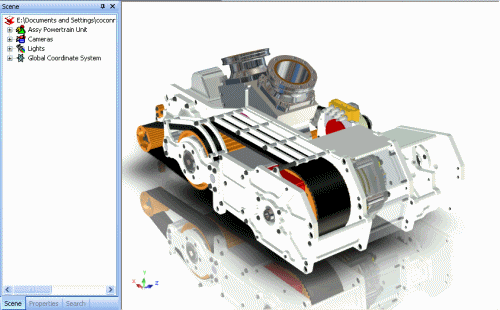
A new Advance Search capability has been added to IRONCAD Version 11 to help navigate product structures in the design. This advance search capability not only searches for assembly, part, and IntelliShape names, but it can even search part properties, suppressed items, hidden items, and custom applied properties. The search results are fast and clearly displayed with a hierarchical display. Search results can be selected and actions can be performed on the selection as if you were working in the normal Scene Browser. In addition, commands like "Locate in Scene Browser" can be performed to quickly direct the user to the Scene Browser location of the selection. Users can save searches to quickly access them at a later point in the design or other designs. Since the Search capability was designed within the IRONCAD Tab display of the Scene Browser, the tab can be undocked and positioned at any desired location that fits the designers work flow. This advance search capability reduces design time by allowing the user the ability to search within the content to find the critical data they need without spending time browsing the structure for the information.
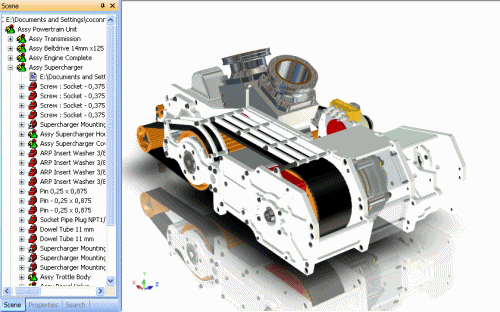
Search Browser Example
Double-Click Edit Dimension Support
IRONCAD Version 11 supports double-click editing on common dimensions applied in the design environment reducing mouse-clicks which can improve the overall design time. Double-click editing can be performed on 3D dimension, Sizebox Dimensions (including Assembly, Part, and IntelliShape levels), TriBall Position Dimensions, and 2D Sketch Constraint Dimensions.
Double-Click Dimension Edit Example
Direct Drill-Down to Part/IntelliShape on Click
Within complex assembly structures, many mouse-clicks are usually necessary to drill down to the selected design state that the users will be editing. IRONCAD Version 11 has introduced direct drill-down hot-keys to access the part and assembly levels. The users and hit the Ctrl or Atl keys when left-click selecting to directly access the part or IntelliShape levels respectively. This direct access can drastically reduce design time by allowing the user to efficiently access the necessary data during the design modifications.
Alt and Ctrl Key Direct Selection Example
Prevent Editing Setting on Parts/Assemblies
Sharing designs within a design group is a common practice in 3D modeling. However in some instances, it may be desired to lock users from accidentally modifying designs or standard components. New settings at the part and assembly level have been added to disallow edits at the respective levels. This setting prevents the user from access the data below the level that the setting is applied. Visual indicators in both the Scene Browser and in the graphical selection area have been added to help the users to determine if the setting has been applied.
Prevent Selection Example
Assembly/Part Cursor Mouse-over Icons
In IRONCAD's continuing effort to help users clearly understand the design data, new mouse cursor feedback has been added to denote part and assembly levels in addition to the current IntelliShape and Face levels. These icons clearly denote if a user has selected a part or an assembly to help navigate the next action in the users design step.
Multiple Select Quick Access Property Browser Capability
Improving on the Quick Access Property Browser added in version 10, new support for multiple selection has been added to various control in the Quick Access Property Browser (slider controls and list boxes). This improves the overall design modifications on multiple objects which in turn helps reduce design times.
Re-sizable File Open/Save Dialogs
Re-sizeable file open/save dialog support has been added to allow the user the ability to re-size the dialogs to help display more items. This helps the user navigate the data to find the desired designs or data easily.
Re-sizeable Dialogs Example
Light Quick Access Property Browser Support
The Quick Access Property Browser has been enhanced to support selected Lights and multiple selected lights. This allows the user quick access to change common light settings on a single light or multiple selected lights which reduces time spent in setting up your environment for visualization and photo-realistic rendering.
Lights Property Browser Example
Undo/Redo Camera History Capability
IRONCAD cameras have been improved to support full undo/redo capabilities on camera position changes including switching cameras and switching between active split window panes. This allows the user the ability to easily cycle through the camera history that could have been set to show critical elements of the design.
Camera Undo/Redo Example
Parameter Expression Linking to Excel Spreadsheets
Users can now link parameter expressions to an excel spreadsheet to drive IRONCAD models parametrically from a common excel file. Users can build excel documents that may be generated automatically using customer inputted data from a website configuration for example. This excel spreadsheet can be referenced in IRONCAD to parametrically drive the IRONCAD model by using a parameter expression (i.e. excel("c:\parameter.xls","Sheet1","A2"). This capability reduces user errors that may arise by copying and pasting data from one source to another.
Detailed Sketch Improvements
Offset Constraint and bidirectional offset Support
The 2D sketch offset command has been enhanced to support an offset constraint and the ability to create a bidirectional offset. The offset constraint allows the user to create an association between the originating curve and offset curve. This association allows the user to modify the offset curves where both will update to maintain the offset distance. This allows the user the ability to create more complex sketches that have offset associations to make edits easy without the need to recreate the geometry. The bidirectional offset allows the users the ability to use the originating curve as a reference while offsetting in both directions from this curve.
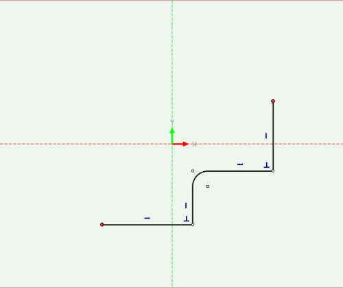
2D Sketch Offset Improvements Example
2D BSpline Enhancement
Many improvements have been made on the BSpline tool to allow the user the ability to create more complex geometry by allowing for more control and accuracy. This improvements include:
Tangency Magnitude and Angle - New handles have been added to the BSplines to allow the users the ability to adjust the magnitude and angle of the spline at endpoints and control points. Users can adjust both dynamically, or can independently adjust the settings by selecting the specific individual handles. Accurate input can be set by right-clicking on the tangency handles.
Dimension Constraints to Spline Endpoint and Control Points - Constraint dimensions can be applied directly to the spline endpoints and control points to parametrically drive the spline based on the users definition.
Dimension Constraints to Tangency Magnitude and Angle - Constraint dimensions and angle dimensions can be applied directly to the spline tangency handles to parametrically drive the splines based on the users defined rules.
Mirror Constraint Support for Splines - The mirror constraint tool has been enhanced to support splines within the command. This constraint will properly update the spline when edits are made in either the original curve or mirrored curve.
Projection Constraint Support for Splines - Projection constraints are now supported for splines expanding the design relationships that the user can create that refer to other 3D geometry.
Display Curvature Improvements on Splines - Curvature display has been enhanced to support display for the Maximum Curvature, Inflexion Points, and to display the Envelope Curve of the Curvature. These help the user understand the spline curvature to allow for better and more accurate designs.
Offset Tolerance Accuracy Control - The Offset Tool has been enhanced to support the offset tolerance settings. This can control the accuracy of the offset geometry and the number of interpolation points created in the offset.
2D Sketch Spline Improvements Example
Reference Point Capability in the 2D Sketch
2D Reference Point capability has been added to the 2D Sketch. This will allow users the ability to create reference locations to build 2D Sketch geometry from. The points can be created directly on the 2D Sketch or can be created from projections and projection constraints allowing the user to refer to existing 3D geometry.
2D Sketch Quick Access Property Browser Command Updates
The Quick Access Property Browser has been enhanced to allow additional capabilities in various 2D Editing commands. These changes allow the user to have more control on the curves to perform the command on and allows additional options from the previous version enhancing the design capability for the user. These improvements include:
Move/Copy Editing Tool - This tool has been converted to the Quick Access Property Browser which allows the user to change the selection of the curves to perform the action on, allows copy option, allows the user to maintain constraint relations within the move/copy, and allows the user to denote the move/copy point to point distance as well as an incremental changes from the current location of the curves.
Rotate Editing Tool - This tool has been converted to the Quick Access Property Browser which allows the user to change the selection of the curves to perform the action on, allows copy option, allows the user to maintain constraint relations within the rotation, allows the user to unlock common constraints that prevent the rotation such as Horizontal and Vertical constraints, and allows the redefine the rotation center.
Scale Editing Tool - This tool has been converted to the Quick Access Property Browser which allows the user to change the selection of the curves to perform the action on, allows copy option, allows the user to maintain constraint relations within the scale, and allows the user to redefine the scale location point.
Mirror Editing Tool - This tool has been converted to the Quick Access Property Browser which allows the user to change the selection of the curves to perform the action on, allows copy option, allows the user to maintain constraint relations within the mirror, allows the user the ability to constrain the mirror, and allows the user to redefine the mirror about location.
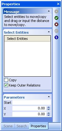
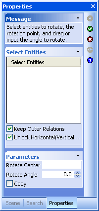
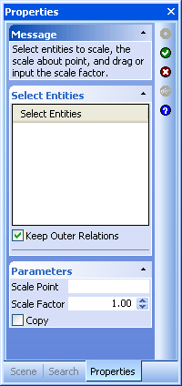
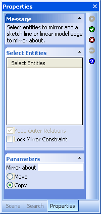
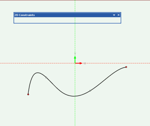
Move, Rotate, Scale, and Mirror Command Options
Linear and Circular Pattern Tool
New Linear and Circular Pattern tools have been added to the 2D Sketch environment allowing the user to create patterned geometry in the Sketch. This initial implementation allows the user the ability to select the desired patterned curves and definitions to create a non-associative pattern. Future enhancements will be added to support pattern constraints.
2D Sketch Linear and Circular Pattern Example
Constraint Dimension Improvements
Midpoint Constraint - A Midpoint constraints can now be added to endpoints to lines and 3D geometry.
Arc Length Dimension Constraint - Users can now define a Arc Length Dimension on arcs in the 2D Sketch. This can be used to parametrically drive the arc information.
Arc Angle Dimension Constraint - Users can now define the Arc Angle Dimension constraint to parametrically drive the angle of arc in the 2D Sketch.
Solving Mode Options - Certain modification to constraint dimensions can cause the curves to update in different manners based on the 2D Solving mode defined. In IRONCAD Version 11, the user can specify the default solving mode for sketches as Standard or Minimum move to satisfy the modification in the manner that is desired by the user.
Profile Indicator and Constraint Indicator Visual Improvements - Updates have been performed on the user interface for the profile and constraint indicators to better display the associations to the users. Icons have been adjusted to display smaller to avoid display issues with the curve geometry. In addition, the some constraints have been improved to display next to other constraints to avoid overlapping conditions with other constraints or curve endpoints. Curve highlights have been added when the user mouses over the constraints to clearly identify the geometry associated to the constraints.
Show Profile and Constraint Improvements - Improvements have been made to the "Show" property page of the 2D Sketch for profile indicators and constraints. The user can independently control which indicators to display. Also, the user can specify to show/hide constraints and constraint indicators to clarify the sketch geometry.
Smart Constraint Creation Improvements - The Smart Constraints added in IRONCAD Version 10, have been improved to support selective creation of specified constraints and dimensions. Users can select the type of constraints to automatically create during the creation and editing of geometry.
Snap to Sketch Improvements - More options have been added to the Snap settings for the "Snap to Sketch" elements. This allows the user to better control which elements to snap to when creating and editing geometry.
Constraint Behavior Improvements - Behavior changes in the sketch have been enhanced to allow for more predictable results when creating and editing geometry.
Trim/Extend - During the trim and extend of geometry with constraints applied, rules have been updated to handle the existing constraints. In addition, trim or extend operations that end with a point on another line will automatically create coincident constraints.
Line-Line Dimension Constraint - The Dimension Constraint tool has been updated to create predictable results when selecting a line-to-line dimension. Selecting a line-to-line will create an angle constraint. Dimension from point-to-point or point-to-line will create linear dimensions.
2D Sketch Constraint Improvements Example
Detailed Part Design Improvements
Part-to-Part Boolean Feature Editing Support
Enhancing the current IRONCAD boolean capabilities, IRONCAD V11 now supports the ability to retain features of both boolean parts for editing after the boolean. The users will be able to access the features in the Scene Browser to make edits to the boolean part.
Part-to-Part Boolean Feature Example
Loft Improvements for Centerline Guide Curve
Improvements have been made in the IRONCAD lofting capabilities to support centerline lofts, loft guides, and match point definition. These enhancements allow for the user to build more complex loft features to meet their design needs. In addition to the loft enhancements, automatic references can be made during the loft creation that can make subsequent edits easier by maintaining initial design rules.
Loft Improvements Example
True/Real Thread Creation on Cylindrical Surfaces
In addition to the existing graphical threads, IRONCAD V11 allows the user to create associative threads to cylindrical surfaces. This allows users the ability to build true threads that can be detailed or manufactured downstream in the process. Users can define the profile of the thread to meet their specific requirements.
True/Real Thread Creation Example
Variable Pitch Helix Spring Support
New improvements have been made to the Helix tool to support a variable pitch. This variable pitch can be defined in the beginning, middle, and end of the spring definition allowing the user to build the specific spring desired.
Variable Pitch Helix Example
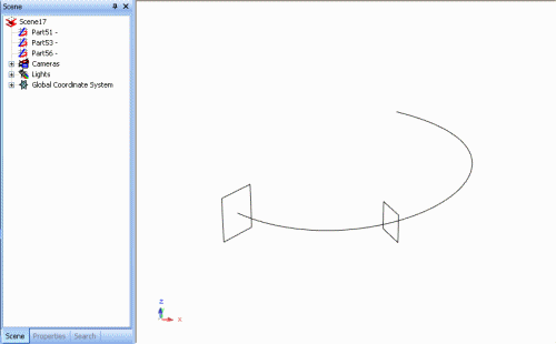
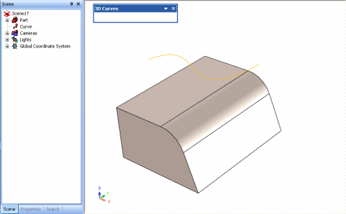
2 Plane Projection to Single Curve Capability
Users can now create a projection curve that is created by combining a projection of 2 curves in intersecting planes. This projection curve can be used to create surfaces in the desired orientation.
2 Plane Projection to Single Curve Example
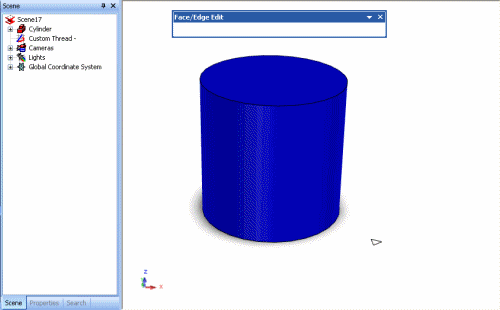
Wrap 3D Curve to Cylindrical Surface
A new command has been added to allow the user to wrap a 3D curve onto a cylindrical surface. This wrap command is different than a projection in that it basically unrolls the surface to a flat, projects the curve onto the flat surface, and then wraps the surface back to the cylindrical shape.
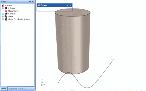
Wrap 3D Curve Example
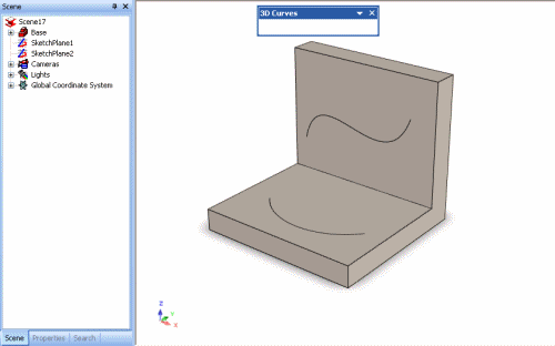
Project 3D Curves to Multiple Surfaces
The 3D Curve Projection tools have been enhanced to support the ability to project 3D Curves onto multiple surfaces. This allows the user to build the desired 3D Curves that can be projected onto multiple surfaces that will used in other operations.
Project 3D Curves To Multiple Surfaces Example
Import/Export Improvements
STL Export Smoothness Control for Rapid Prototyping - During Export of STL files, new export options have been added to control the quality of the STL generated file. Users are able to control the surface accuracy, angle tolerance, and surface deviation.
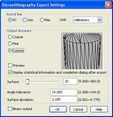
STL Export Options
Imported Parts Default to Triangulated Mesh - A new option has been added to the Import Options (found on the Import Dialog) to allow for the imported parts to be set to Triangulated Mesh. This setting can correct facet issues that are sometimes present in imported data due to tolerance differences in the applications.
Combine All Shapes to Single Shape - In some design processes, it is required to import data from other systems to build designs around this data. In many cases, the structure of the data is not needed in the users design. However, the user needs the real data to reference and build accurately around. A new option in IRONCAD allows the user to import models and collapse the models structure to a single shape. This can greatly improve the performance in IRONCAD since it can reduce large structure trees into a single nodes.
Combine Only Surfaces Shapes - In addition to the option above, users can control the import to only collapse the surface part structure to a single shape. This is useful when the import generates many surface parts due to tolerance differences between applications. Collapsing these structures to a single shape can greatly improve performance by eliminating the large model structures and memory usage.
Maximum Sewing Tolerance Settings - A new option has been added to control the tolerance level of the stitching that can occur between surfaces during import. This tolerance can allow the user to better control if the surfaces will be stitched into solids by appropriately adjusting the settings to their needs.
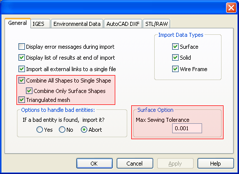
Import Options Added
2D PDF Improvements
Many improvements have been implemented in the 2D PDF export (both manual export and 2D PDF reader) to better support communication of the IRONCAD drawing files. Quality settings have been added for Image Resolution and Image Quality to allow for high quality printing from the PDF.
3D PDF Improvements
Improvements to the 3D PDF have been implemented to support better communication to members outside the design team. Double-sided rendering support has been added to allow for users to easily open the 3D PDF's without having to change settings in Adobe Reader.
3D Positioning Improvements
TriBall Copy/Link to Multiple Point Location Support
New improvements to reduce design times have been added to the TriBall positioning tool. One of these improvements includes the new multiple point creation capability for Copy and Link. The users can invoke the Copy/Link to multiple locations command on the right-click menu of the TriBall center point. The user can then use the power of the TriBall to define locations anywhere the TriBall can position. These locations can be precise inputs, snap points, or any general location. After placing all the desired locations, the user simply accepts the command and the copies or links are generated. Since this command is enabled on the TriBall, the operation can be performed at the Assembly, Part, and IntelliShape level.
TriBall Multiple Copy/Link Example
TriBall Reference Location Capability
In addition to the Copy/Link at multiple locations capability, the TriBall has also been enhanced to support multiple reference locations. Using the existing Attachment Point capability, the user can create multiple locations on assemblies, parts, and IntelliShapes that can be used as a reference point locations for the TriBall. These reference points are locations where TriBall operations such as translation and rotations can be performed. The users can quickly toggle through these points using the "Tab" key or can directly point to a specific location in the Right-Click menu of the TriBall. In addition to the accessing the attachment points, the TriBall can be used to create the locations during the design process. This capability saves the user time from going between different commands. Combining this new reference point TriBall locations with the existing Smart Assembly capability, can provide a powerful combination to the users by allowing quick drag and drop position locations and automatic orientation of data.
TriBall Reference Location Example
Position TriBall Center Command with Multiple Shapes Selected
The existing "Position TriBall Center" command has been enhanced to allow the command to work on multiple selected shapes. This enhances the existing functionality to work in a multiple selected shape environment helping the user work faster in their design process by applying multiple actions in a single command.
TriBall Position Center With Multiple Selections Example
TriBall Short-Cut Assignments Added
Short-Cut assignments have been added to the TriBall Right-Click menu to allow the user to create custom short-cuts that can improve their design efficiency by reducing the mouse clicks in accessing common design process commands
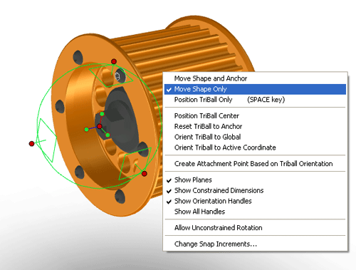
TriBall Move Shape Visual Highlight Improvement
Many times the users may use the TriBall "Move Shape Only" command or may be automatically set in this TriBall command (this would be in cases like the Smart Assembly for example). In some instances, the users may not understand that they are in this mode of the TriBall. To correct this issue, the TriBall has been enhanced to clearly mark the differences between the "Move Shape and Anchor, Move Shape Only, and Move TriBall Only by setting a unique color for each respective mode.
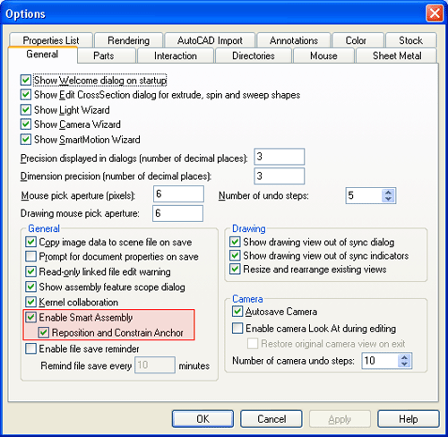
SmartAssembly Connection Options
User options have been provided to control the default drop behavior of the Smart Assembly. Users can set the drop action to position and size only or can have the drop action set to position, size, and associate. This allows the users to define the correct drop actions for their design application process or needs without customizing the Smart Assembly add-in logic.
SmartAssembly Stretch Improvements
Improvements have been made in the Stretch command to correctly handle associations made during the Smart Assembly command. These improvements correct the stretch to work in the proper manner. In some instances in order to achieve this, the associations will automatically be removed saving the user many steps to correctly stretch their components.
3D Visibility Improvements
Background Real-time Rendering Improvements
Improvements to the Advanced OpenGL/Direct3D rendering mode have been made to enhance the visualization of models during the detail design process. These improvements can also be used to take quick screen captures to communicate your design to members outside the design team without the need for full realistic rendering. These improvements include:
Shadow Plane Support - Shadow planes can be added to help display the ground plane for your models. This gives the user an added bit of realism to the model without impeding on the performance of the system.
Real-time Shadow Plane Example
Reflection Plane Support in 3D - Reflection planes can be added to the rendering environment to give an added bit of realistic rendering to your design. The users can control settings such as blur, fading, attenuation.
Real-time Reflection Plane Example
Real-time Shadow Mapping Support (Direct3D Only) - New functionality to display a real-time shadow casting on your model during rotation has been added. This capability adds in the realistic display of the model in addition to helping display aesthetic issues that may be present in the real design.
Real-time Shadow Mapping Example
Line Antialiasing - User can now enable line antialiasing in the Advanced OpenGL/Direct3D rendering mode to sharpen the edge display of the models.
Full-screen Antialiasing - Full-screen antialiasing can be enabled to sharpen your design when lines are not drawn. This aids in screen captures that represent your design in communications outside the design group.
Direct3D/OpenGL User Setting Option
Different operating systems and graphics cards can perform better based on the OpenGL or Direct 3D settings. Windows Vista for example has superior graphical performance under Direct3D versus running under OpenGL. IRONCAD V11 allows the user to change this setting to ensure that the best performance can be achieved on your system.
Hide Part/Assembly Identification in Scene Browser And Show Selected support
With the introduction of Hide Commands in IRONCAD Version 10, users have requested the ability to denote the hidden elements in the Scene Browser. IRONCAD Version 11 now supports a visual indicator in the Scene Browser that denotes between visible and hidden components as well as suppressed components. In addition, we added the ability to select hidden components in the scene browser and show the selected. This allows the user the ability to selectively show and hide the desired component in their design process.
Scene Browser Hide Icons and Show Selected Example
2D Technical Drawing Improvements
Part/Assembly Hide Support for Quick Views
The Part/Assembly Selection for View Creation has been updated to fully support the Quick View creation type. This enhancement allows the users to fully take advantage of the fast view creation capabilities and the single scene environment design. The combination saves the users time in creating many external linked files and time generating more precise views during the design and layout stages.
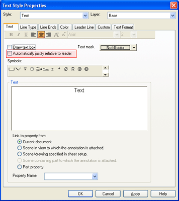
Text with Leader Justification
A new style option has been added to Text with Leaders to allow for automatic justification of the text during creation and edit. This new option saves the users time in adjusting the justification settings when creating text with leader annotations.
Edit Section Line Capabilities to Redefine Section Lines
Improvements to the Section capability have been made to allow for the user to redefine the section line information after the creation. This allows the user to move the section line and staggered section line segments.
Edit Section Line Example
Multiple Broken-Out Section View Support on Single Views
The Broken-Out Section view has been enhanced to support multiple section views on a single view. This allows the user to create multiple broken-out sections at different depths to clearly define the desired information without the need for multiple views saving the user space and time wasted in view creations.
Multiple Broken-Out Section View Support Example
Shaded View Option Flag During Creation of the View
In many detailed designs, the users may want to convey a more realistic representation by shading the views. Normally this would require the user to create the views and then select each view to shade. A new option has been added on the view creation dialog to shade the views being created. This will automatically shade all the views in a single command instances saving the user manual steps in the past.
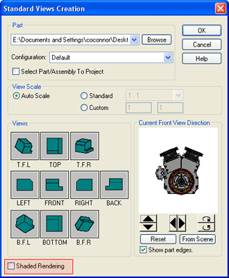
Fast Advanced OpenGL/Direct3D View Creation Preview Capability
When dealing with large assembly data, the preview in the view creation dialog could take extra time in the generation process since it was using a legacy rendering mode. This time could increase when the users toggled the front view direction to change the orientation or to verify the correct orientation. If the user is using the Advanced OpenGL/Direct3D mode in the 3D Environment, new improvements have been made to reuse this information in the preview window reducing the generation time. This allows the user to work faster in generating the views which will help in the overall design time.
Double-Click Edit of Drawing Sheet Tab Name
Users can now rename drawing tabs by simply double-clicking on the tab names and hitting enter to accept the change. This follows standard editing in spreadsheets like Microsoft Excel.
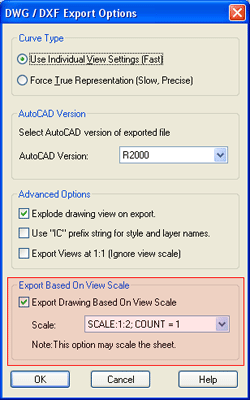
Export Drawing to DWG/DXF Allows Page Scale Option
A new export option has been added to the export options for DWG/DXF to export the drawing at a predefined page scale. This allows you to set the page scale when exporting to match that of your views. This ensures accurate measurement of your drawing when being read by other users.
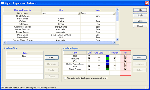
Do Not Print Control for Layers
During the design, it may be necessary to convey design note information on the drawing that is not normally represented in the final output. To accommodate for this, a new layer option has been added to allow the user to specify if a layer will be printed.
Undo Support for Text Edit and Movement Changes
Undo support has been added to account for text edit and position changes on the drawing. This allows the user the ability to easily undo changes to the text information and position without the need to recreate the data.
Broken View Zig-Zag Size Control
New handle controls have been added to the broken view Zig-Zag lines to control the position, size, and angle of the lines. Users can independently change the location of each line while maintaining the angle control for both line. In addition, the users have snap highlights to precisely align the positions of the lines.
Broken View Zig-Zag Size Control Example
Edit Scene from Drawing Loads Scene in Configuration Specified
Editing the scene from the drawing is a common practice in IRONCAD. In the past, the edit scene command would load the scene at the last used configuration setting. IRONCAD Version 11 has enhanced this capability to load the scene in the configuration that the drawing view was specified in. This allows the user to quickly access and edit the scene in the configuration that they wish to perform the action.
Edit Scene from Drawing Loads Scene in Configuration Specified Example
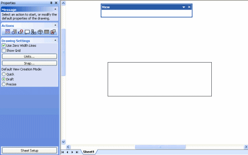
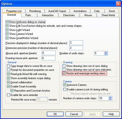
Resize Views on New View Creation Settings
Global option have been added to allow the user to set the default resizing behavior of views when adding new views to an existing sheet. This new option eliminates the constant dialog pop-ups that would display in the view creation process saving the user an extra mouse-click.
Smooth Edge Option on Drawing View Styles
Enhancing the quality display on the drawing, a new option for Smooth Edge visibility has been added. The users can set the line type and color for both the visible and hidden smooth edges. This helps enhance the drawing display by clearly denoting the smooth edges from real visible edges.
Smooth Edge Option on Drawing View Styles Example
Operating System and System Updates
Windows Vista Support
IRONCAD Version 11 has been updated to support Microsoft Vista. Vista support offers the users to take advantage of the latest OS improvements including graphical rendering improvements under Direct3D.
Advanced OpenGL/Direct 3D Upgrade Improvements
Upgrades to the underlining graphical engine in the IRONCAD Advanced OpenGL/Direct 3D have been performed. HOOPS 3D from TechSoft3D has been updated to the latest version 16.23 which improves real-time graphical performance. Details on improvement in the HOOPS engine, visit http://developer.techsoft3d.com/current/release.html.
Unicode Support
IRONCAD V11 has been updated to support Unicode. This improves language translations between different operating systems around the world.
Subsystem Upgrades
Parasolid Modeling Kernel Updates - Updates to the Parasolid kernel have be implemented. These updates include various improvements to the modeling geometry as well as support for new version. Files up to version 19.1 can be imported and exported.
ACIS Modeling Kernel Updates - Updates to the ACIS kernel have be implemented. These updates include various improvements to the modeling geometry as well as support for new version. Files up to version 18 can be imported and exported.
D-Cubed Component Updates - Component of the D-Cubed offering including the 2D DCM, 3D DCM, and the 3D CDM have been updated to the latest version to improve performance and reliability of solving and collision.
TechSoft 3D HOOPS Toolkit Updates - Updates to the latest version of the HOOPS toolkit allows users to export and share IRONCAD scene files in the latest HSF format. This allow users to share data with other applications such as a viewer while taking advantage of the latest visual and performance improvements.
Spatial 3D Interop Translators - Updates to the many import/export options available in IRONCAD (including IGES and STEP) have been updated to the latest versions offered from Spatial. This update improves the reliability of the import/export interoperability between CAD systems.
PTC Granite Updates - IRONCAD's add-on option for the PTC Granite has been updated to the latest version supporting version 5.0 and Wildfire 4.0.
CATIA V5 Read/Write Support - IRONCAD's add-on for CATIA V5 supports Read versions R2 through R18 and Write versions R6 through R18.
Unigraphics Updates - Updates to IRONCAD's add-on for Unigraphics has been updated to support versions 11 to 18 and version NX1, NX2, NX3, NX4, and NX5.
3rd Party Integration Updates
Algor DesignCheck Professional
A new add-in offering has been supplied with IRONCAD Version 11 for Algor DesignCheck Professional. For users that need more than the free add-in of Algor DesignCheck Part Static-Stress Analysis, this new optional add-in provides much more power and benefits to accurately analyze users designs. Information about Algor DesignCheck and DesignCheck Professional can be found at www.ironcad.com/explore/solutionpartners/analysis/algor. For information about purchasing Algor DesignCheck Professional for IRONCAD , please contact IronCAD or your local reseller.
Softeacher International
Based on The IronCAD Essentials - Professional 5 Day Training, Softeacher is now offering a free one day training for IRONCAD available to any IRONCAD customer. The one day course provides a basic understanding of 3D-modeling within IRONCAD as well as how to detail a model in 2D. This free training teaches the basic fundamentals of IRONCAD to allow new customers a jump start in learning the full power of IRONCAD. To access the download, visit IronCAD Gold Partner - Softeacher International.
Print3D Corporation
Print3D Corporation is a global provider of custom rapid prototyping services, providing CAD users an advanced set of software tools that integrate directly into their modeling environment. Print3D’s powerful real-time pricing engine makes quoting and ordering parts as easy as printing a document.
The free Print3D for IRONCAD plug-in gives you the ability to price and order production parts of your designs directly from your IRONCAD workspace. The plug-in adds a Print3D command to the application menu and toolbar. The software’s pricing algorithms calculates instant, guaranteed quotes on all the CAD components you have open in IRONCAD. Use the plug-in dialogue box to specify paint finishes, metallic coatings, or special handling instructions. To access the download, visit IronCAD Gold Partner - Print3D Corporation.
IronCAD Labs Beta Versions
CAXA DRAFT
CAXA DRAFT 2D Design application has been added to the IronCAD Labs Beta program to allow users to test and provide feedback on future products offered to customers worldwide. CAXA DRAFT has been updated with a new user interface, full association with IRONCAD 3D Files, full Bill of Material associations to IRONCAD 3D Data, full support for transferred dimensions for the IRONCAD 3D Data, and many more 2D improvements. Visit the IronCAD Labs community section for details about the updated version and beta rules or contact IronCAD for details.