IronCAD 7.0
Key New Features
Getting Started with IronCAD 7.0
This document contains some of the new features in the IronCAD 7.0 release. "Show-Me" tutorials have been provided with this documentation that will walk through simple examples of the new functionality. "Show-Me" tutorials are visually rich, yet extremely compact movie files, which transform static text help files into vivid product demonstrations. Each "Show-Me" opens in its own unique Flash enabled browser window (requires Flash Player plug-in). Click on the following link in order to test your browser for Flash support: Flash Test. The following "Show-Me" tutorials will begin to play automatically once you select the "Show-Me" icon. Additional controls in the "Show-Me" can be used to pause, stop, fast-forward, and rewind.
Assembly features are very similar to existing part features except they can affect multiple parts, are created in the context of an assembly/scene, and the feature definitions do not pass down to each part. Assembly features can be Extruded Cuts, Spin Cuts, or Custom Hole Shapes. Assembly Features are by definition, a machining process that is processed on the assembled component and not performed on each individual component.
How to - To create an Assembly Feature, right-click and drag an existing H-shape catalog item (or Custom Hole) onto a selected assembly or scene. In the resulting pop-up dialog, select Drop as Assembly Feature. Select the options for the Assembly Feature Scope (Select the Assembly/Parts that will be affected by the Assembly Feature) and select Ok. Use the IntelliShape handles (or Custom Hole Properties) to define the size and shape of the Assembly Feature. Right-click on the Assembly Feature for options like Editing the Assembly Feature Scope and Create Part Feature. Note: Multiple Assembly Features can be placed on and Assembly/Scene which will display in the Assembly Feature Group in the Scene Browser.
Convert to Part Features - Multiple Part Features are similar to Assembly Features since they affect multiple parts, however multiple part features will reflect in each individual part definition. You can convert Assembly Features into part features by right-clicking on the Assembly Feature and selecting Create Part Feature.

Assembly Feature Display
Variable Radius Blends allow users to create more advance blending to meet the needs for manufacturing. Variable Radius Blends create multiple points with varying values along a single edge.
How to - Select the Blend command from the Face/Edge Edit Toolbar (or right-click on a selected edge and select Blend). In the Blend Type field, select Variable. Click on the edge to add points (or select the Divide into Equally Spaced option and specify the number of points to add multiple points). Click on the Points or the Endpoint Arrows/Points to modify the values and positions (drag the points to change the position visually). To Delete Points, right-click on the point and select Delete.

Variable Radius Blend
The Variable Wall Thickness option for shelling, extends the shell command to help meet the needs for more complex manufacturing needs such as plastic mold designs. Users can set a desired shell thickness along with specifying a wall thickness on specific selected faces.
How to - Select a part to shell. Right-click and select Shell (or select the Shell command from the Face/Edge Edit Toolbar). Select the faces you wish to be open during the shell (which will highlight the edges in Green for the selected faces). Specify the Wall Thickness for the part. If desired, select the Wall Thickness Option on the Shell Ribbon Bar to specify alternate wall thickness for specific faces. Select the faces to have different wall thickness (which will highlight the edges of the faces selected blue) and then set the values for the selected faces. Note: To select multiple faces to specify values, hold the Shift Key down while selecting the faces.
Variable Wall Thickness Shell
Options are now available for the IntelliShape Loft to allow for lofts with guide curves. Users will be able to create or edit lofts to include 3D Curves as guides for the loft profiles. Note: The 3D Curves must pass through a point on each profile of the loft in order to become a guide curve.
How to - There are multiple ways to add guide curves to lofts:
Creation via Profiles: Create multiple 2D Shape Profiles that define the desired loft shape. Create 3D Curves (as many as desired) that intersect at a point on each of the 2D Shape Profiles. Multi-select the 2D Profiles using the Shift Key and the Left-clicking, then right-click on one of the profiles and select Loft. In the resulting Wizard, select Add Guide Curve option and select the 3D Curve to add. Click Finish to complete the adding of the Guide Curves command and select Ok to finish the loft.
Creation via Adding to Loft: Create a loft shape using the IntelliShape loft command. Right-click on the resulting loft IntelliShape and select Create 3D Guide Curve. Use the 3D Curve command to create a guide curve that intersects at a point on each profile of the loft. Select Ok on the 3D Curve command to finish the curve creation and to add it as a guide curve.
Editing: After creating a loft shape, right-click at the IntelliShape level of the loft and select Edit Guide Curves. Right-click on the Guide Curve and select Edit.
Loft with Guide Curves
There are multiple enhancements to IntelliShape Handles in IronCAD that will help increase productivity during modeling.
Enhancements include:
Handle Icon Information - Mouse-over handle display on IntelliShape Sizebox Handles will display the current direction (Length/Width/Height).
Dimension Display - IntelliShape Sizebox Handles will display dimensions when the handle is clicked. Users can use the dimension as a reference or right-click on the dimension to edit the values for the selected handle.
Multi-Select Edit - User can multi-select IntelliShape Sizebox Handles (while holding the Ctrl-Key) and modify all handles simultaneously. This is valuable for modifying a shape in a symmetrical manner.
Snap Increments - IntelliShape Sizebox Handles can snap to increments, which are specified by the user. Select Handle Snapping under the Format pull-down menu to set the increments (Unitless or Specified Unit increment). When dragging IntelliShape Sizebox Handles, hold the Ctrl key to invoke the snap increment.
IntelliShape Handle Display/Enhancements
Improvements have been implemented in the 3D SmartDimensions to increase file performance (Open/Save, Link/Unlink, Assemble/Disassemble) when many 3D SmartDimensions are in use. In addition, improvements have been implemented to maintain the preservation of dimensions through these types of operations as well as Catalog interaction. Users will also notice that 3D SmartDimensions can be selected directly from the scene (when the "Show SmartDimensions" option is on in the view pull-down menu) without having to select the shape that owns the dimension. Additionally, the 3D SmartDimension Tool on the toolbar will stay remain when creating dimensions.
New options on the Center Point and Orientation Handles of the TriBall to allow Midpoint Snaps are available to help aid in positioning and orientation.
How to - After selecting the shapes you wish to position, turn on the TriBall (F10). Right-click on the center-point (or any orientation handle) of the TriBall and select To Midpoint, and then the desired option (Midpoint of Edge, Midpoint of Two Points, or Midpoint between Two Faces). Click on the desired inputs to position the shape to the Midpoint.
TriBall "To Midpoint" Option
2D Profile AutoCAD Preview Import
The AutoCAD DXF/DWG import dialog (activated by importing within a 2D Profile) will now have a preview pane that allows the user to visually inspect the import as well as the changes when layers are turned on/off.
AutoCAD DXF/DWG Import Dialog
2D Profile (IntelliShape Profile) Placement Options
When creating a 2D Profile or IntelliShape, new options for the plane placement are available.
Options include:
Pick Point - Pick a point in the scene or on existing geometry for the plane placement (Existing placement behavior).
3 Points - Pick 3 Points where the plane will pass through.
Planar Face Though Point - Select a planar face and a point for the plane to pass through.
Planar Face Offset - Select a planar face and input value to offset face.
Planar Face at Angle - Select a planar face and edge and input angle.
Tangent to Cylindrical Face Through Point - Select cylindrical face to be tangent to and a point to pass through.
Plane Parallel to Curves - Select two curves to create a plane which is parallel to the selected curves.
Plane Normal to Curve Through Point - Select a curve and the location point for a plane normal to the curve at the selected point.
Bisection of Two Parallel Faces - Select two parallel faces to create a plane at the bisection location of the faces.
2D Profile Creation Wizards

2D Shapes that were created in the scene can be used to create IntelliShapes (Extrude, Spin, Sweep, and Loft). New Wizards are available after right-clicking on a 2D Profile and entering an IntelliShape command. During the IntelliShape creation, new options are available for association behavior from the original 2D Shape (Copy Profile, Link to Profile, or Consume the Profile) and the ability to Add/Remove from specified parts in the scene. Below is an example of the new wizard options for the 2D Shape Right-click Create options.
How to - Create a 2D Shape in the scene. Right-click on the 2D Shapes to access options for Extrude, Spin, Sweep, and Loft (The Loft option requires the user to multi-select two or more 2D Profile Shapes). Select the desired option to launch the profile wizards.
Profile Behaviors:
Copy - Create new IntelliShape from the profile and create a copy of the 2D Profile in the Scene (No association between the IntelliShape and the profile).
Link - Create a new IntelliShape from the profile and create a link association to the original profile geometry. This will allow edits in the original 2D Profile which will update any IntelliShape linked to it.
Consume - Create a new IntelliShape and remove the original 2D Profile.
Extrude 2D Profile Wizard
2D Profile Interaction/UI Enhancements
Fillet Support for Arcs
Fillet support on the 2D Profile has been extended to include fillets between lines and arcs. Using the existing 2D Fillet Command, fillets can be applied between lines and arcs to create a smooth line segment.
Profile Grid Update
The 2D Profile Grid user interface has been updated to help aid in 2D Shape creation. Major and Minor Grid line display is available and can be specified by the user. Snapping to the grid will allow snap to both the Major and Minor Grid lines. The X-Y Reference Grids have been visually improved (also, they can be used in offset operations).
2D Profile Grid
2D Profile Automatic Look-At
2D Profile creation will orient the Grid to the X-Y Plane orientation automatically when no parts/assemblies are located in the scene.
Updates to the parameter table have been implemented to help aid in the creation and editing of user-defined parameters.
Updates include:
Browser UI in the Parameter Table - The Browser in the parameter table helps identify which parameters are related to assemblies/parts/features. Users can use the browser to drill down to specific parameters.
Highlight Selection Option - The Highlight Selection Options allows users to highlight parameters that may be used for common operations or are commonly modified.
Sortable Columns - Users can sort columns of the parameter table to help aid in locating desired parameters (Double-click on the Column Header).
Parameter Table
Users will be able to create a face-face fillet surfaces within a surface part (the surface can be open or joined to form an edge). Constant and Variable radius fillets are available operations.
How to - Select the Face-Face Fillet from the Surface Toolbar. Select the fillet type. For Constant: Select two surface faces located on a part. Select on the Orientation Arrows to change the Fillet Tangent direction. Enter the Fillet Value and select Ok. For Variable: Select two surface faces and an edge (for the reference location) on a part. Select on the reference edge to place points for the variable (Use the Reverse Orientation option to change direction of the Reference Edge). Select the points to enter the Fillet Value and select Ok to finish the command.
Fillet Surface Editing
Extend Surface
Additional surface modification tools are available to aid in surface creation/editing. The "Extend" Surface allows a user to extend a selected edge of a surface along the tangent direction.
How to - Select the Extend Surface from the Surface Toolbar. Select the edge of the surface you desire to extend. Drag the handle to visually extend the surface. Enter a value or percentage in the Extend Surface ribbon bar for precise input. Use the right-click handle options for extended controls.
Extend Surface Handle Edit
The Project 3D Curves tool allows users to project 3D Curves onto surfaces or part faces to be used in other operations.
How to - Select the Projection Curve from the 3D Curves Toolbar. Select the Face/Surface you wish to project onto. Select an edge on any part to define the projection direction (Use the Projection Curve ribbon bar to change the direction along the edge). Select the 3D Curve to project and select Ok to finish the command.
Project 3D Curve
Iso-Parametric Curve
Creation
Users will be able to extract UV curves from an existing surface shape based on a coordinate location, pick point, or distance along a surface edge.
How to - Select the Iso-Parametric Curve option from the 3D Curves Toolbar. Select the surface that you wish to create the 3D Curve. Select the direction along the surface edge which determines the 3D Curve direction (Use the Flip Direction to toggle directions). Select the point on the surface where you wish to create the curve or enter the percentage value along the edge to place the curve. Click Ok to finish the command.
Iso-Parametric 3D Curve Creation
Intersection Curve Creation
The Intersection Curve Tool allows a user to create a new 3D Curve based on an intersection of parts/surfaces.
How to - Select the Intersection Curve option on the 3D Curves Toolbar. Select two surfaces/faces that intersect. Select Ok to create the intersection curve.

Intersection Curve Creation
Formula Based Curves
Users will be able to generate a curve based on formulas that are defined by the user. This tool is useful if the 3D Curve needs to define a specific set of parameters/formulas (For Example: A Helix can be defined using a Formula).

Formula Curve Dialog
Scene selection improvements have been implemented to allow the user to select IntelliShapes without the need to use camera zoom operations. This helps users select small negative IntelliShapes in Part designs without zoom operations. Selection on edges of negative IntelliShapes and positive shapes will select the negative IntelliShape by default (Previous versions of IronCAD would select the positive shape, which would cause the user to zoom in/out to select faces of the negative IntelliShape).
A new Conical Sheet Metal Shape has been added to the sheet metal catalog. This shape can be used to create cylindrical or conical sheet metal parts that can unfold into a flat sheet (in addition, sheet metal cut-operations can be performed on the conical sheet metal). Note: Add Stock cannot be added to the conical shape for this release.
Conical Sheet Metal Creation
Users will be able to access view curves (to place on layers and styles) that were created from the projected 3D geometry on the drawing. This will allow users to place curves on layers that may be hidden or to show highlighted areas on the drawing. In addition, the curve styles can be modified to display different line types. The Edit View Curves option will only be available in precise views on the drawing.
How to - Select a view. Right-click and select Properties. Select Precise view quality display and select Ok. Right-click in the sheet and select Edit View Curves (Notice that the views that are not set to precise will be dimmed). Select the curves that you wish to change styles or place on a specified layer. Select the Properties button from the toolbar (or right-click on the curves) to access the styles and layers. Note: Use the Eye-dropper Tool to copy/paste properties to other curves.
Edit View Curves for Styles and Layers
When a drawing is out-of-date with the scene, notification display (Border on Views and BOM) and messaging is available to the user. Views and BOM Tables that are out-of-date are displayed with a border around the view/BOM. When opening a drawing or windowing to a drawing, a dialog will display that notifies the user that the drawing is out of date (Users can choose to hide notification).
Out-of-Date Notification Borders
Dimensions transferred from the scene to the drawing can be edited from within the drawing. Users can mouse-over transferred editable dimensions (shown in the Highlight Display) and right-click to edit the dimension value.
To Edit Dimension on Drawing:
To edit all editable transferred dimension on the sheet, select Edit Dimension by right-clicking on the drawing sheet or from the Edit pull-down menu. Once a user enters the edit dimension command, a command bar will appear and dimensions on the sheet will display as shown in the figure below. Non-editable dimension will show in a light shaded color (dimmed version of the dimension color). Right-click on each dimension (or double-click) to enter a new value. The new value will be displayed while within the Edit Dimension command as well as outside of the command. Highlight display of edited dimensions will contain an *asterisk in the upper right corner of the displayed border. When all dimension edits are finished, select the Ok button to exit the command. Geometry in the drawing will not update until the drawing views are updated. Scene geometry will be updated as the dimensions are modified (the scene will be saved when the drawing is saved). Note: Edits cannot be saved when the scene file is a read-only file.
The Types of editable transferred dimension are:
Profile Constraint Dimensions
3D SmartDimensions
Non-Editable Dimension include:
Sheet/Drawing Dimensions
Transferred Dimension with Expressions (Dimension used in Parameters as driven dimensions).
Reference 3D/2D SmartDimensions
Editable Dimension Highlight Display

Dimension Display in Edit Dimension Command
Users will have options to define individual views to be draft or precise quality. This capability allows users to leave certain views in draft mode for visualization (projected curves are based of the facet representation and the creation is normally faster than precise) while having other views in precise mode for exporting or for final printing (precise will create/export true line geometry).
How to - Right-click on any view in the drawing and select View Properties. Under View Quality, select the desired quality for the view. To set the default settings for newly created views, right-click in the sheet and select Sheet Setup. Select the View Creation Quality.
View Quality Mode
IronCAD's industry leading catalog technology is now available in the 2D Drawing. Users can create Groups (containing curves and text) and drag and drop into the catalog for reuse (sheet curves and text can be added to the catalog as well as groups). Standard catalogs containing mechanical, electrical, architectural, and miscellaneous catalogs are included to help aid users.
How to - Create the desired set of 2D Curves and Text. Select the set of curves and text and select Group from the Shape Editing Toolbar. Create a new catalog in the drawing from the Catalog pull-down menu. Drag and Drop the 2D Group into the new catalog.
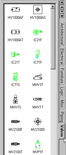
2D Drawing Catalogs
2D Curves and Text on the drawing can be grouped for reuse, scaling, and positioning. Groups act as sheet elements that can be in front of or behind other elements on the drawing. The groups can be dropped into 2D Catalogs for reuse and can be scaled by dragging the group shape handles.
How to - Select the desired 2D Curves and Text to be grouped (Left-click and Drag in the sheet to multi-select elements on the sheet). Select Group from the Shape Editing Toolbar. Use the Bring to Front or Send to Back options to display the group, relative to other items in the drawing. Use the Group Handles to scale the group. Left-click and drag on the group shape to position or to drag into the catalog. To edit the contents of the group, use the Ungroup option then edit the items and re-group the elements.
2D Closed Profile Drawing Curves have additional options for applying hatch and fill styles. Users can apply a color fill and a hatch pattern to a closed profile to create a specific representation on the drawing. Users can group the curves to reuse later from the catalogs.
How to - Create a closed profile 2D Curve. Right-click on the 2D Curve and select Hatch/Fill.

2D Curve Fill/Hatch
A broken-out section is part of an existing drawing view that is used to remove material to a specified depth in order to expose inner details of a model. A closed profile, usually a spline, defines the broken-out section. Users can input an exact depth or specify a depth by referencing a location in another view.
How to - Select a view to create a broken-out section. Select the Broken-Out Section Tool from the View Toolbar. Draw a closed profile using the 2D Technical Drawing Tools that define the desired section area. Select the Define Depth option. Specify the desired depth or select the option to define a depth from a location of a different view. Select Ok to create the broken-out section.
Broken-Out Section View
Section View Creation on Isometric Views
Standard Section View Creation can be performed on Isometric Views to return a true section view. When performing a section view, the Horizontal and Vertical Section lines will align to the isometric view angles. The resulting section view will return a true section of the geometry.
How to - Click on the Section View Tool from the View Toolbar. Select Horizontal or Vertical as the section direction. Select the location for the section line in the Isometric view (Notice the section line automatically adjust to align to the angles of the Isometric view). Select Ok to create the section view. Left-click to place the section view.
Section View on Isometric View
General View Orientation Tools
Additional controls are available on General View Creation dialog to aid in view orientation for custom views. Standard Views and the current Scene orientation can be selected to use as a base point.

General View Creation Dialog
Options are available to reattach views that have broken alignment. Users can reattach views to the default alignment or create new alignments (horizontal and vertical by center of the view).
How to - Select a view that has a broken alignment. Right-click on the view and select View Alignment and the option to align by. For Horizontal and Vertical, select the view to align to.

View Alignment Reattachment Options
Rotate View
Drawing views can be rotated to desired angles independently of the projected view orientation.
How to - Right-click on the view to rotate and select Properties (or select View Rotation in the right-click menu). Enter the desired rotation angle and select any option desired. Select Update Dependent Views if you also want to update any views that were created from the view you are rotating (projected views, for example). Select Rotate Centerlines with view if you want centerlines and center marks to rotate with the view.
Rotate View
Scale/Rotate Tools Active on Views
2D Editing Scale and Rotate tools can be used on views in the 2D Drawing.
How to - To Scale: Select a view (or multiple views). Select the Scale Tool from the 2D Editing Toolbar. Left-click and drag for visual scale or right-click and drag to input a scale factor. In addition, right-click on a selected view and select View Scale to enter the view scale. To Rotate: Select a single view. Select the Rotate Tool from the 2D Editing Toolbar. Left-click and drag and enter a rotation value in the View Rotation dialog that pops-up. Select options for dependent views and centerlines. In addition, right-click on a selected view and select View Rotation to enter or modify the view rotation.
View Scale and Rotate
Change Front View Orientations
Views created from the Standard View Creation can be modified using the Edit View Orientation. Views can be added or deleted and the Front View Direction can be modified.
How to - Right-click on a view created from the Standard View Creation Tool. Select Edit View Orientation. Add/Remove views and/or modify the Current Front View Direction. Select Update to update the views in the drawing.

Edit View Orientation Update
True Isometric Dimensions can now be created using standard dimension tools in the drawing. Views that have the Create True (Isometric) Dimension option checked can use SmartDimensions to create the Isometric dimensions.
How to - Right-click on a Isometric view and select Properties. Check the Create True (Isometric) Dimensions under Dimension Creation. Click Ok to exit the properties dialog. Use the SmartDimension tools to place dimensions on the Isometric View.
Arc Length Dimension Creation
The true length of an Arc can be dimensioned using the Arc Length Dimension Tool. Users can specify the Arc Length Dimension display as Acute or Obtuse along with the Arc Length symbol placement as Above or Prefix.
How to - Select the Arc Length Dimension Tool from the Dimension Toolbar. Select an Arc to dimension. Right-click on the dimension and select Properties/Arc Length Style to adjust any property information (like Acute or Obtuse Alignment).
Arc Length Dimensioning
Dimension Reattachment
Handles
Handles have been added to dimensions to allow reattachment to other points/edges after the dimension has been placed.
How to - Left-click on a dimension in the 2D Drawing. Left-click and drag on the Reattachment Handles to align to new points/lines. Note: Dimensions referring to lines (not endpoints) only display one reattachment handle and can only reattach to other lines.

Dimension Reattachment Handles
Extension Line Handles
Handles have been added on dimension to allow users the ability to adjust the extension line distance visually on the drawing. Precise values for the extensions can be entered in the dimension properties.
How to - Left-click on a dimension in the 2D Drawing. Left-click and drag on the Extension Handle to adjust the length.

Extension Line Handles and Properties
Maximum/Minimum Distance
for Circular Arc Dimensions
Dimensions can be created between circles and arcs by referencing the minimum and maximum points in addition to center points on the selected circles/arcs (IE. Dimensions between concentric circles can be created).
How to - Select the SmartDimension Tool from the dimension toolbar. Shift+left-click on a circular arc then left-click on a second arc. Right-click on the dimension and select Properties. Select the Start and End Arc placement under Arc Options.

Maximum/Minimum Distance on Circular Arcs
Ordinate Dimension Display Enhancements
Ordinate dimension placement options have been enhanced to allow for easier placement of ordinate and stagger ordinate dimensions. Click handles are available on the ordinate dimension to turn on/off staggered display. Drag options can be used to control the movement of ordinate dimensions when positioning.
How to - Create Ordinate dimensions on geometry in the drawing. Left-Click on the square Stagger Handle to turn on/off the stagger for the selected dimension. Left-click and drag the round handle to position the stagger in the desired location. Hold the Ctrl or Shift key to invoke constrained movements when dragging selected handles.
Ordinate Dimension Handle Options
Dimension Display Enhancements
Tolerance Display Scale
The Tolerance display has new options to allow the user to define the size of the tolerance based on the Font or percentage of the dimension size.
Tolerance Size Options
Trailing Zero Display Option
Options in the Dimension Styles are available to control the display of trailing zeros on dimension (Ex. 1.250 versus 1.25).
Text Display (On/Above and Parallel/Horizontal)
Text and Dimension Styles have options available to define the text orientation (On/Above and Parallel/Horizontal) to the dimension line. These options are also available on the right-click properties of dimensions and text to individually control elements.
Text/Dimension Display On/Above and Parallel/Horizontal
Drag Alignment for Dimensions
Snap options are available on dimension arrows to allow users to align individually selected dimensions.
How to - Select a Dimension on the drawing. Left-click and drag on the Dimension Arrow. Move the cursor over the dimension to align to. The dimension will automatically snap to the dimension.
The Centerline Tool is available to allow placement of centerlines between two selected entities and torus shapes.
How to - Select the Centerline Tool from the Annotation Toolbar. Select two edges to place a centerline between two selected entities or select a cylindrical face (or torus) to place a centerline.

Centerline Creation Tool
Text and Text with leaders can be specified to read input from Scene or Drawing properties referenced in the drawing. This referencing allows users to setup template information that refers to File Property information.
How to - Create the desired text element on the drawing. Right-click on the text and select Properties. On the Text Tab, select where you wish to link properties from. Current Document refers to the properties located in the Drawing Properties of the file. Scene in View is available when a Text with Leader is pointing to a view (not geometry) and it refers to the File Properties of the scene. Scene/Drawing Specified in Sheet Setup is referring to the document specified on the Sheet Setup page located under Use Document Properties From. Scene to which the Annotation is Attached is available when a Text with Leader is attached to a geometry of a particular scene file referring to its File Properties. The Property Names can be selected from the available options or can refer to a custom file properties defined by the user (The property name may need to be typed in manually). IronCAD creates a custom strings in the text identifying it from other text. Each option of the links will have a different String ($PRPDrawing:"Text", $PRPScene:"Text", $PRPSheet:"Text", $PRPView:"Text" - "Text" is the area that can be related to custom properties entered by the user). This String can be placed inline with other text and formatted as a single text element.
Text Property Referencing
Layer updates have been implemented to allow users the ability to lock layers to disable editing. In addition, locked layers can be displayed visually as dimmed to denote the locked status.
Locked Layer Display
New Alignment Tools are available to align selected groups of Dimensions and Item Bubbles. Selected entities can be aligned Left, Center, Right, Top, Middle, Bottom, Distributed Vertically, and Distributed Horizontal based on the text sizebox.
Alignment Tool
BOM Table enhancements have been implemented to aid in custom formatted BOM tables.
Options Available Include:
Merge Cells - Cells in the BOM can be merged to define custom layouts for property information or user defined column information.
User Defined Columns - User defined columns can be used to create formula based columns similar to Microsoft Excel Formulas.
Alignment Tools - Additional format options are available to align cell information based on customer specifications.
BOM Alignment - Options are available to set the Alignment behavior for the BOM when Rows and Column are added. User can specify Top Left, Top Right, Bottom Right, and Bottom Left as the default Alignment Anchor of the BOM (when rows or columns are added, the specified anchor location will remain stationary and the BOM will update in the unlocked directions).
Formatting Enhancements - Additional controls to define multiple Header Rows and other formatting options for Cells are available.

BOM Table Interaction/UI Enhancements
Enhancement have been added to the Hole Table in the following areas:
Box Selection for Holes - Users can now box select the desired hole set to be used in the hole table.
Reorder Based on Column - Users can reorder a hole table by columns.
Multi-Section Hole Table - Users can create multi-section tables (similar to the BOM table).
Multi-Select Edit Items - Users can multi-select items used in the hole table to make edits from the selection group.
Hole Table Enhancements
Section line display options are available to omit the section line, display as thin-thick, and to display labels at staggers. These options are available in the Default Elements and on the right-click options of the section line.
Section Line Display Options
The Surface Finish Tool now has the ability to be placed in open areas of the drawing and on Dimension Extension lines.
Surface Finish Placement Options
New Arrow Type support for additional standards requirements are available for the Datum Target/Feature.
Datum Target Display Options
A new import option is available on the drawing to import Style/Layer information from existing IronCAD Drawings. This option allows users to easily transfer template style/layer information between drawings.
During export to DWG/DXF, a new option is available to export the drawing as an exploded drawing. This allows for easier integration into CAM software applications that read DXF/DWG data.

Export DWG/DXF as Exploded
When saving a drawing to a new directory (Save As), users have an option to copy associated scene files to the new directory. This option will relink the associated scene files to the newly saved drawing file. This enhancement helps user start new design projects using existing scene and drawing files.
Copy Linked Scene Files to Drawing Folder
Updates to the Default Elements and Style/Layer property pages have been performed to allow for additional options for 2D elements in IronCAD.
Updates Include:
Line Width Display - Line Width will be displayed visually to users when creating new line thickness in the Style Pages.
Text Format - Options for Text Format have been added to the Label Styles.
Additional Default Elements - Additional default elements have been added to allow users additional control on displaying newly created elements in the drawing.
Additional standard ANSI and ISO Hatch Patterns are available in all standard drawing templates under Hatch Styles.

Standard Hatch Types
Enhancements have been made to improve operations in the 3D Scene to enhance performance when dealing with larger assemblies. These enhancements include 3D rotation, interaction in the scene browser, improved open/save performance, and improved performance when many dimensions are contained in a file. In addition, enhancements have been made to improve operations in the 2D Drawing. These enhancements include improved view creation/update, Precise/visual based views, improved section view creation/update, and general selection/highlight improvements.
Global Reference Datum Planes are available in IronCAD Scene files.
These planes can be used for:
Drag & Drop - Drag & Drop from the Catalog will allow snap placement on each plane.
Positioning:
TriBall - TriBall positioning by default will snap to the Datum Planes while displaying the position information.
3D Curve - 3D Curve Creation will snap to the Datum Planes while displaying the position information.
Position Dimension - Turn on Position dimensions (Under View Menu) for referencing Global positions for Part/Assemblies.
Sizing - Using IntelliShape Handles, hold the Shift Key to allow snapping to the Datum Planes Axis.
Starting Profiles - Right-click on any Datum Plane to create a profile based on the selected planes origin and orientation as well as an offset profile.

Datum Plane
To Use the Datum Planes:
Scene Template - Start a new scene and select the pre-defined templates labeled color-datum.ics. This will start a new scene with the selected color and with the datum turned on.
Turn on/off - Under the View pull-down menu, click to show the datum planes in each view pane of any scene.
When the datum planes are on, selections (like TriBall, Drag & Drop, Handle Snap, etc) will highlight and will select the datum planes. If geometry is present in the scene, highlighting will revert to the geometry in the scene over the datum planes.
Default Drag & Drop behavior if dropped in the scene (not selecting a datum) will drop to the 0,0,0 location of the scene.

Datum Plane Highlight
To select a Datum Plane from the scene:
Select on the outside edge of any datum plane to highlight the datum plane.
Right-click on the outside edge of the datum to access options:
Hide/Show Plane - Hides/shows the selected plane from the scene view.
Show/Hide Plane Gird - Shows/Hides Grid on selected Datum Plane (removes Major and Minor Ticks).
Create Profile - Create profile based on the selected planes origin and orientation.
Create Offset Profile - Create a profile based on the selected planes origin and orientation at an offset distance.
Format Datum Planes - Format the display of the datum planes including Grid line, Grid spacing, Datum Size, Datum Behavior, and Snap options.
Format Datum Plane Options:
Grid Spacing - Set the Major and Minor grid spacing along with the Snap option of each.
Plane Size - Set the datum plane size (Manual Size) or select Auto Size to auto size to geometry created in the scene.
Datum Plane Format
The World Coordinate Axis is a visual reference for the user in the scene for determining the global orientation in 3D. The World Coordinate Axis rotates when the scene is rotated giving the user a reference during all movements. The World Coordinate Axis can be displayed separately in each view window in the scene.
Options provided on the World Coordinate Axis are:
Left Click - Left-click on the X, Y, or Z arrow to set the Look At camera position along the selected axis.
Shift Left Click - Shift-Left-click on the X, Y, or Z arrow to set the Look At camera position along the selected axis in the reverse direction.
How to Turn on/off - Select the World Coordinate Axis option in the view pull-down menu to set the display options in the selected scene view.

World Coordinate Axis
Visual display on linked instances has been updated to display the linked instance highlight during drill down on shapes. This helps the users visually understand how shapes are referenced in other linked shapes.
ACIS 12.0 - IronCAD's Dual Kernel support for ACIS has been updated to ACIS version 12.0.
Parasolid 15.0 - IronCAD's Dual Kernel support for Parasolid has been updated to Parasolid version 15.0.
Upgrade IGES - Spatial 3D InterOp IGES Translator has been updated to version 12.0. Support for color information is now available on import.
Upgrade STEP (Support AP203/214) - Spatial 3D InterOp Step Translator has been updated to version 12. In addition, support for both AP203 and AP214 import format is available.
Upgrade AutoCAD 2004 - Import/Export support for AutoCAD 2004 is now available. In addition, import of AutoCAD 2005 is supported.
HSF Viewable Scene Information - Support for the OpenHSF standard viewing format is implemented in IronCAD Scene Files. Export options are available to export scene files as Hoops Stream Format (HSF) to be viewed in supported HSF format viewers. Supported HSF Viewers can reference IronCAD Scene viewable files through standard access calls.
IronCAD 7.0 includes a Free IronCAD Native .ics File Format Viewer. Users will be able to visualize, measure, explode, and perform cuts and cross sections (and more!). In addition, Informative Graphics now offers support for both IronCAD Scene and Drawing files in their standard viewers. ModelPress is a free 3D viewer that can be used to distribute throughout companies to access IronCAD Scene Files.
IronCAD's publishing tool, IronWeb, has been updated to support publishing of viewable HSF (3D Scene) and PDF (2D Drawings). In addition, new template based formatting is available to allow for custom website design. Companies can create custom templates for corporate look and feel using style sheets and XSL formatting.
IronWeb Publishing Tool
Updates to the supported 3Dconnexion motion controller devices have been implemented to resolve rotation issues in the 3D Scene (Center of Rotation has been adjusted for IronCAD Camera's). Note: IronCAD 6 Product Update 2 and 7.0 support the 3Dconnexion 3DxWare Drivers without additional add-on drivers. To download the 3DxWare Driver for your 3Dconnexion motion controller, visit http://www.3dconnexion.com/downlink.asp.
IronCAD 7.0 officially announces the release of the IronCAD Application Programming Interface (ICAPI). The ICAPI provides a robust and easy-to-use programming interface that allows users access to functionality within IronCAD. Through ICAPI programmable interface functions, a user of ICAPI can perform almost all the main tasks that an end user can perform through the graphical interfaces provided by IronCAD. In addition, a user can customize and enhance many additional capabilities with very few restrictions, for instance; to customize UI behaviors or add users' data can be done through Extension Data Objects (EDO), attribute or a callback mechanism. To make ICAPI easy to use for customers, an object-oriented design has been adopted. External objects more or less map to objects that an end user sees on the screen during an interactive session of IronCAD. These objects form a clear hierarchy that is identical to what an end user would expect from what they see on screen: Therefore, it is intuitive for a user of ICAPI to traverse through the objects to reach the one he/she wants to perform a certain function on. Functions associated with a particular object are grouped into multiple interfaces. Each interface provides a number of functions that logically perform similar kinds of operations that are associated with that object.
Sample IronCAD API projects are included in IronCAD 7.0. The samples aid in some tasks which are commonly performed in IronCAD that demonstrate the methods of using the Automation capabilities of the IronCAD application. These samples are provided on an as is basis and IronCAD makes no representations or warranties regarding these samples. Any licensed user of IronCAD is free to use any or all of these samples in connection with building applications that are related to the family of IronCAD applications; and is granted a royalty free, non-exclusive license for these samples, or parts thereof. Intellectual property rights of the samples remain with IronCAD. Any confidentiality provisions of the IronCAD license apply to the samples.
Samples Available:
SmartSnap Assembly
Selection Tool
Link Manager
Boolean Options (Subtraction/Intersection)
Copy/Move IntelliShapes to New Part
External Link Display
Modeling Helper (Multi-Part Kernel/Facet Conversion, Difference Boolean)
Helix Display (EDO)
Drawing Creation