CAD Built for Structural Design Using Aluminum Profiles
Apr 30, 2018 |
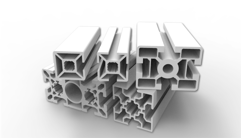
All extrusion profiles used in structural design are not created equal, nor are the designs of the structures made up of the extrusions. Nevertheless, many CAD solutions on the market today provide standard tools for the design of aluminum extrusions and the construction of the structures made up of extrusions.
On the other hand, CAD software that acknowledges the complexity of structural design, and is equipped with specialty tools, can help designers that work with aluminum extrusions get to market faster and improve collaboration with their customers.
All Design Tools Are Not Equal
Designing structures with aluminum extrusions can be labor intensive since many CAD solutions need long design times based on the processes built into the way the CAD system works traditionally. They typically require users to parametrize the model by manually applying mating relationships.
These systems also don’t tailor performance demands required when dealing with thousands of detailed aluminum extrusion profiles in both 3D and the 2D detailing process.
In addition, these tools typically require CAD domain experts to perform the design. Very rarely do you see customers interfacing with these CAD systems to lay out concepts.
The IronCAD Mechanical Design Extension for the IronCAD Design Collaboration Suite (DCS), however, was specifically designed to address the needs of equipment manufacturers engaged in structural design using aluminum extrusions. Dedicated tools are available for custom profile creation, intelligent connections, and profile visibility for performance. And, best of all, it is easy to understand and use.
A CAD Platform with Dedicated Tools for Structural Design
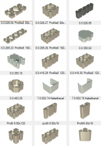
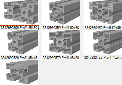
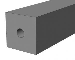
IronCAD Mechanical extends IronCAD’s drag-and-drop Catalog design by developing tools specific to the building and assembling of extruded profile structures. The custom steels tool allows users to use a predefined set of profiles, or they can upload their own profiles for company-specific designs.
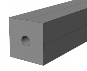
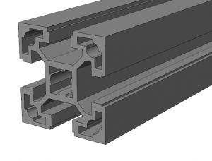
Once added, users simply drag and drop extrusions into the 3D design environment and specify lengths and end conditions like tapers. Intelligence can be added to allow automatic positioning and alignment behaviors when dropping in subsequent profiles. This intelligence is also used to eliminate the tedious mate positioning found in the traditional CAD process. Using this approach, users can quickly construct a structure with modular pieces, much like building a Lego model.
Tools for Assembly Design Needs
IronCAD’s Unified Design Environment is ideal for the assembly design of aluminum structures. Simply add more parts and dynamically create assemblies by grouping parts.
There is no need to build individual files for parts and assemblies, nor does one have to insert parts into assembly files. Tools like the TriBall allow for the dynamic repositioning of parts to desired locations and orientations, as well as creating additional components or patterns of components.
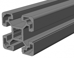
IronCAD is designed to handle large assemblies graphically and IronCAD Mechanical extends this by providing visual tools for profile elements. Alter the display of the profiles to be Simplified, Simple, Intermediate, or Detailed to meet the various needs in your process. Setting to Simplified can drastically burst your performance in process. The, use the Detail setting to apply a detailed representation for accurate construction.
IronCAD’s Stretch tool provides an easy mechanism to quickly stretch an entire structural assembly to a desired length. Other tools like the Analysis tool can provide accurate weight and center of gravity calculations for verification. IronCAD’s Multiphysics can be added to extend the verification process for true FEA functional analysis.In addition to dedicated tools for structural extrusions, IronCAD Mechanical provides tools to streamline the entire structural design process. Tools for drilling holes through multiple parts while adding fasteners to fit are provided with the drag-and-drop process. All the tools for creating geometry can be set up to add the correct part naming nomenclature and additional properties that will automatically populate a detailed Bill of Materials (BOM).
Extending the Design to Collaborate Outside of Engineering
IronCAD’s approach using drag and drop and handle push-and-pull modification allows the application to be useful of departments other than just the engineering groups.
Custom catalogs can be populated with standard elements that can be used to design/bid directly with customers, providing a major advantage. This also reduces the overall design process since the conceptual designs can be used directly with the engineering groups to finalize the design already constructed versus starting from scratch.
Other departments can use the designs to create marketing content like brochures or even assembly instructions. Designs can be shared with clients using a Web browser for visual communication and final verification of designs.
Combine all of these capabilities in a single system, and you can imagine how much more productive your structural design process might be. To see such as system in action, watch our webinar highlighting many of the innovations IronCAD has incorporated to support the structural design process.
Or, contact IronCAD today to find out how the IronCAD DCS can be used to increase the productivity of your structural design process.