What’s New in 2016 PU #1
May 31, 2016
Quick Links
- Productivity Enhancing Design
- Sheet Metal Improvements
- Detailing Improvements
- Additional Improvements
IronCAD Design Collaboration Suite (DCS) 2016 Product Update #1 extends the overall productivity introduced in the 2016 release. Many customer driven requests to improve your overall design productivity have been focused on especially general day-to-day commands as well as sheet metal and detailing your products.
Please review the new features below for a more comprehensive list of enhancements in the 2016 Product Update #1 release. To review the enhancements provided in 2016, visit IronCAD DCS 2016 New Features.
Productivity Enhancing Design
TriBall Center-point Snap to Nearest
Often when you are designing, you will use the TriBall to position objects. One of the common tasks it to move the object to a Midpoint of an Edge or a vertex. The TriBall provides the ability to drag the center-point snap to these locations (or precise input on the right-click menu). To speed up this common task, you can now drag the center-point of the TriBall and hold the Shift Key to enable “Snap to Nearest.” Simply drag onto an edge and the TriBall will snap to the nearest point or midpoint on the highlighted edge. Release the mouse drag and it is precisely placed without having to move the extra amount to locate the points.
Available in:
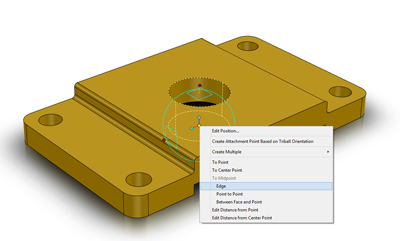
Midpoint Right-Click Menu Quick Access
The right-click menus for various IntelliShape Handles and the TriBall have been updated to provide faster access to select the Midpoint options such as To Edge, Point to Point, Between Face and Point. Previous versions used a sub menu that would expand when selected. The new behavior provides quick access and reduces the mouse movement required to access this common command for positioning and referencing.
Available in:
![]()
![]()
![]()
![]()
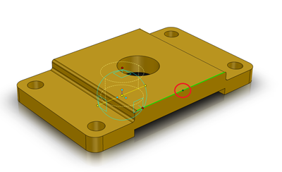
Midpoint Highlight for Visibility
When snapping to the midpoint of an edge, it was often time consuming to locate this location along an edge. The new visibility improvement will highlight the midpoint when you select the edge for commands like dragging the TriBall to the edge or snapping IntelliShape handles to an edge.
Available in:
![]()
![]()
![]()
![]()
Part/Assembly Sub Groups
IronCAD has always had the ability to create groups of various selected components such as parts, features, and assemblies. Once created, these groups reside in the current scene to allow you to select the groups quickly for operations. The new improvement will allow these groups to become a sub element of a part or an assembly so that they can be stored in externally linked files or catalogs. For example: If you selection contains all the features under one part, you will be asked if you want the group to be created under the part (similar to a folder concept). The same option will be provided if you select parts/assemblies that are under the same assembly. This provides a new capability to group elements for common operations that may be performed later to simply organize your parts/assemblies.
Available in:
![]()
![]()
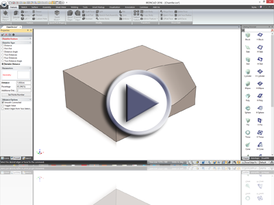
Variable Edge Chamfer
The Edge Chamfer command has been enhanced to support different input along the selected edge. You can select a 2 Point (Distance), 4 Point (Distance-Distance Settings), 2 Point (Distance Angle) and a powerful variable distance with any number of points along the edge. This capability opens up the flexibility to modify geometry to more complex conditions without using typical cutting operations.
Available in:
![]()
![]()
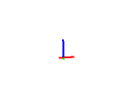
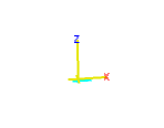
Attachment Point Visibility Improvements
The Attachment Points which are used to provide intelligent Smart eBehaviors to elements have been enhanced to provide better visibility. The indicator has been color coded to indicate the X and Z axis and when it is active (edited), it will display the X and Z indicator. This helps in identify the orientation and directions of the attachment point when creating intelligent snap locations on elements.
Available in:
![]()
![]()
![]()
![]()
IronCAD Native Translator Support for BOM Import
The Native Translator which supports native formats such as Inventor, Solidworks, Pro/E(CREO), UG/NX, SolidEdge, has been enhanced to support BOM information stored with these files. For example: Part Number, Description, Material Name, Material Density, and other custom properties can be transferred during the import process into IronCAD Applications. This enhances the reuse of data from other applications without the need to re-input the data for reusable parts or standard parts for example.
Available in:
![]()
![]()
![]()
![]()
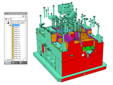
IronCAD Native Translator Support for Graphical Multi-Body Display
In 2016, the Native Translator was enhanced to support graphical input from the native file formats to improve the import speed and to allow selected import of the solid data for editing. This capability has been enhanced to display Multiple Body Parts that are commonly used in structured design applications such as UG/NX, Pro/E, etc. Multiple Body Parts allow user to create many bodies under a single part that can be used to complete a final part or for making an assembly of parts easier to reference (such as structural frames). When importing these into IronCAD Application, the bodies will be accessible in the graphical display to allow for operations such as hide/show to help visibility.
Available in:
![]()
![]()
![]()
![]()
Sheet Metal Improvements
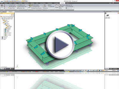
Improve Feature Support and Enhanced Unfold
IronCAD’s Sheet Metal has been improved to support many additional standard operations that are standard in IronCAD’s modeling. For example, users can now apply standard cut features that can affect multiple bends in sheet metal, blends and chamfers on stock corners (not the face edge), and operations such as Trim where you can cut the sheet metal by other objects. This capability was provide by the enhanced unfold capabilities added that can support resultant sheet metal part geometry to flat. In addition, this enhanced behavior improves the unfold operation time to speed up the design process.
Available in:
![]()
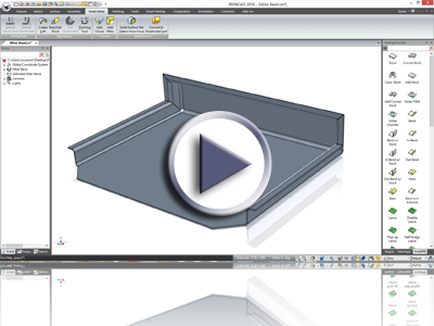
Associative Miter Flange
The Miter tool has been improved to take advantage of the new association behavior added in 2016. When developing sheet metal with this associative settings, the miter tool will create a feature that will update when the source stock or bends are altered. This greatly improves the editing and parametric capabilities of sheet metal in the overall design process.
Available in:
![]()
Miter Across Bend
The Miter tool has been improved to support the Miter across the Bend segment. This adds a powerful option to the miter command to enable more complex geometry for sheet metal design.
Available in:
![]()
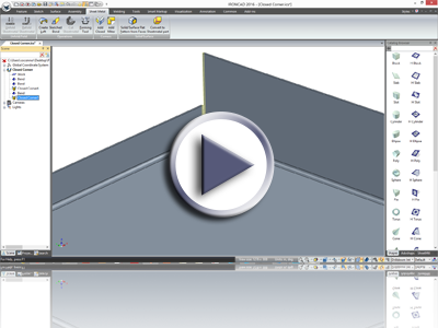
Associated Closed Corner
The Close Corner tool has been improved to take advantage of the new association behavior added in 2016. When developing sheet metal with this associative settings, the closed corner tool will create a feature that will update when the source stock or bends are altered. This greatly improves the editing and parametric capabilities of sheet metal in the overall design process.
Available in:
![]()
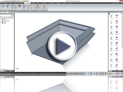
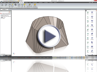
Loft Support for Square to Ellipse
In 2016, the sheet metal loft was enhanced to support formed and pressed bent operations. This version has been enhanced further to support the transition from Square to an Ellipse for the press bent sheet metal. This is a valuable improvement for these types of transitions and even for square to circular that may have angled planes for the loft.
Available in:
![]()
Overlapping Sheet Metal Display
IronCAD supports the ability to overlap sheet metal and unfold it. The new edge display in sheet metal will give you a better indicator once an overlap has occurred by showing the edges of the stocks through other stock elements. This is only for visibility and the unfold will support overlaps when the bends follow a logical rule of construction.
Available in:
![]()
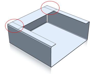
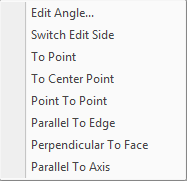
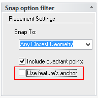
Bend Angle Handle Snap To Options
When right-clicking on Bend Angle Handles, new options have been provided to make alignment to existing geometry easier than ever. Snap to Points, Center-points and align parallel to axis and perpendicular to faces. These new options extend the previous capabilities to align to an edge making it much more powerful especially when aligning at unknown angles and locations.
Available in:
![]()
Detailing Improvements
View Creation Manual Placement
New options have been added to the standard view creation to allow manual placement of the selected views. This capability allow more control in laying our views based on your needs versus the standard fit to scale placement.
Available in:
![]()
View Scale Adjustment During Manual Placement
Using the new manual view placement, you can use the up and down arrows on your keyboard to toggle the various standard scales. This provides an added bit of flexibility when laying out views to fit on a template.
Available in:
![]()
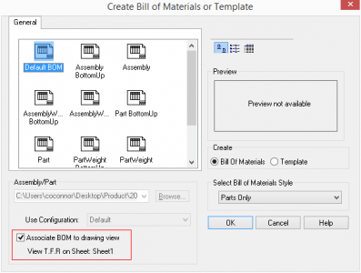
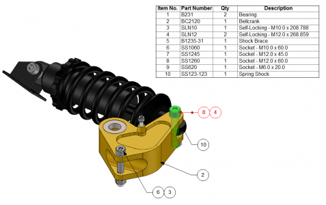
View Based BOM
You can now create Bills of Materials (BOM) based on a selected view in addition to the parts on the view and configurations. This option also provides the ability to have multiple BOM’s on a single sheet of the same scene file based on the view visibility.
Available in:
![]()
Stacked Item Bubbles
You now have the ability to create stacked item bubbles for better clarity on the drawing when calling out BOM line items in a view.
Available in:
![]()
Center Mark from Anchors
When using the Center Mark command, you can now create a center mark based on a particular features anchor that is positioned in the 3D environment. This allows for complex center marks to be placed similar to how sheet metal punch and form marks are created. For example: A slot center can be placed by placing the feature anchor in the center of the slot and then presented in the drawing.
Available in:
![]()
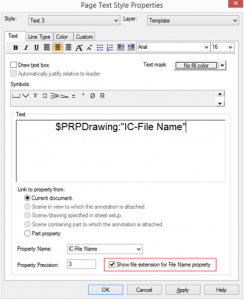
TextBox File Name Extension Control
When using the TextBox capability to extract the File Name, you can now determine if the file name extension is displayed or not. This improves the usability of the command to call out a name without the file name extension.
Available in:
![]()
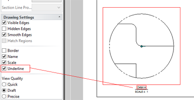
Underline in Section/Detail Names
For Section and Detail views, you can now add underline below the views name to better callout the view.
Available in:
![]()
CAXA DRAFT Improved View Updating
Enhancements have been made to maintain proper dimension associations to geometry for multiple views (on a single sheet) containing configurations.
Available in:
![]()
![]()
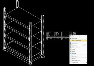
CAXA DRAFT BOM Up/Down Switch
The BOM in CAXA DRAFT now has a right-click option to control the Top-Down and Bottom-Up direction. This improve setup of the drawing and to better conform to drawing standards.
Available in:
![]()
![]()
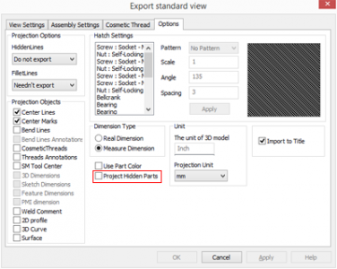
CAXA DRAFT Hidden Part Projection Setting
In the Standard View creation, you can now control if hidden parts in the 3D are projected to the drawing views. In some cases, you may want to have hidden parts displayed in the drawing when you may be hiding items in 3D for better visibility while in other cases you may actually want hidden items to not be projected.
Available in:
![]()
![]()
CAXA DRAFT Graphical Projections
CAXA DRAFT view creation has been enhanced to support the ability to project graphical models (facet models) in the drawing. This allows the ability to use graphical models in 3D (such as Import of Native File Graphic Representation) and reference them in the drawing environment.
Available in:
![]()
![]()
Additional Improvements
Updated Native CAD Translators
With the latest release of the IronCAD DCS, you will have access to the latest versions of CAD file formats using our Native Translator. Version support has been enhanced in following formats beyond the IronCAD DCS 2016 release (refer to the 2016 New Features for other format versions).
- CATIA V5 – V5R8 – V5R26 and V5–V6R2012 – V5–V6R2016
- SolidWorks – 98 – 2016
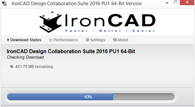
New Download Manger for Improved Access
IronCAD always looks for ways to improve our delivery of our products in both speed and reliability. We have implemented a new download manager that uses the fast and reliable content delivery network from Akamai to improve the speed and success of our product delivery to you. You simply download a small executable file that does not install on your system and when you run, you can track the download as well as pause and restart in case of any network interruptions. Once the download is complete, it will automatically take you to the installation process.
One-Day Free Introduction Training for IronCAD
IronCAD has provided Day 1 of our video training free to all users to help get you started in using IronCAD. This training program is a valuable self-paced video training that teaches the basic of the product. To access the one day training, visit IronCAD Introductory Training. If you are looking for additional training, please contact IronCAD or your local reseller to ask about the full 4-day video training program.