What’s New in IronCAD Design Collaboration Suite 2023 Product Update #1!
Jun 2, 2023 |
IronCAD Design Collaboration Suite 2023 Product Update #1
Revolutionizing Mechanical CAD Design for Industrial Equipment Machinery and Fabrication Markets
IronCAD is excited to announce and share the latest release of IRONCAD 2023 Product Update #1, which contains many exciting improvements and benefits that help customers drive innovation and move designs to production faster. IronCAD continues to strengthen its focus to build upon performance improvements common in large assembly design, functionality improvements in the IronCAD 2D Detail Drawing Environment to be not only more competitive but also more productive, extend key modeling capabilities that continue to advance IronCAD’s flexibility and versatility needed to expand their market reach and user interface improvements that continue to make IronCAD the easiest 3D CAD design product in the industrial equipment machinery and fabrication market.
See for yourself and learn more specific details about this release below:
Quick Links
- General 3D Scene Environment Improvements
- Smart Assembly Intelligence Enhancements
- IronCAD 2D Drawing Improvements
- Modeling Enhancements
- Sheet Metal Design Improvements
- CAXA DRAFT Drawing Updates
- Component and Collaboration Updates
General 3D Scene Environment Enhancements
Performance Improvement Switching Between the 3D scene, IronCAD Drawing, and DRAFT Environments
This improved behavior allows users to effortlessly switch document types while maintaining exceptional speed and responsiveness. With this IronCAD new setting, users can swiftly navigate between the 3D modeling environment and the IronCAD drawing or drafting interfaces, ensuring a fluid and uninterrupted design workflow. Say goodbye to frustrating lags and delays and enjoy a truly efficient and productive design experience. Note: This improvement requires disabling the older Toolbar user interface and making use of the Ribbon Bar Interface.
Available in:
Configuration List Reordering
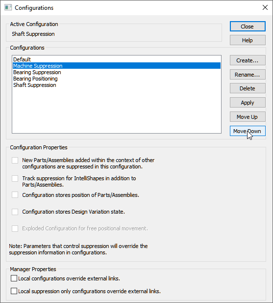
New ability to reorder configurations in the Configuration dialog and pop-up list display has been added. This new feature offers designers and engineers greater control and flexibility when working with complex assemblies and configurations.
Users can now easily rearrange configurations within the Configuration dialog, allowing for a more organized and efficient workflow. Whether you need to prioritize frequently used configurations or restructure the order for easier navigation, the ability to reorder configurations empowers you to customize your workspace according to your specific needs.
Additionally, the pop-up list display has been enhanced to reflect the updated configuration order defined by users, ensuring seamless consistency between the Configuration dialog and the interactive interface.
Available in:
Navigate Through Catalogs Using Keyboard Arrow Keys with Automatic Updates to the Object and Property Viewer Displays
Designers and engineers can now explore catalog items quickly and effortlessly, gaining instant access to crucial information both visually and contextually. With a simple keyboard input with the arrow keys, users can smoothly navigate through the catalog items, while the Object and Property Viewer displays dynamically update to provide real-time details and visual representations of the selected item. Experience unrivaled efficiency and convenience as you swiftly navigate catalogs, access key information, and make informed design decisions with IronCAD’s intuitive keyboard-based navigation.
Available in:
Open Drawing from Right-Click External Link Management Menu
This new option streamlines the design workflow, allowing designers and engineers to access and manage linked drawings without unnecessary navigation. With a simple right-click on the external link part/assembly, users can now instantly open the associated drawing from the External Link Management Menu, saving valuable time and eliminating the hassle of manually locating and opening files from the folder structure.

Available in:
Save As Part/Assembly Added to External Link Management Menu
To improve efficiency in the design process, the Save As Part/Assembly command has been added to the Right-click menu of Parts/Assemblies under the External Link Management menu for convenience to save selected objects as external files.

Available in:
Search in the Parameter Table to Locate Expressions/Names
IronCAD has introduced a powerful search functionality within the parameter table, enabling users to quickly locate text and values throughout all columns, including expressions and parameter names within the IronCAD Parameter Table. This feature boosts productivity by saving valuable time spent searching for specific parameters and allowing direct navigation to the desired parameter for editing.

Available in:
Tooltips for Command Browser for Full-Text String in Dropdown Boxes
While in the Command Browser in IronCAD, it may be common that names or descriptions in the browser for dropdown down list boxes may be cut off due to the size of the browser window. Now you can hoover over the text and a tooltip will appear with the full-length text to clarify the text of the potential selection.
Available in:
Right-Click Drop as Innovative or Structure Part Option
New options have been added to the right-click drag from the catalog on Features to drop as an Innovative or Structured Part. This option speeds up the design process to allow quick selection on the type of part needed for the design at hand. Simply right-click drag and drop with precision locations and select the desired part type to begin your design. Having both modeling types in IronCAD offers versatility in design not found in other CAD Systems.
Available in:
Smart Assembly Intelligence Enhancements
Attachment Point Connector Tool Rigid Movement for Pre-Selected Groups
The Attachment Point Connector Tool provides designers and engineers with powerful methods to manipulate parts and assemblies that are connected using IronCAD Smart Assembly eBehavior.
With the Attachment Point Connector Tool, users can now select and move preselected assemblies and parts as rigid units, maintaining their relationships with surrounding components. This means that complex assemblies can be easily reconfigured without the need to manually rebuild or recreate connections, saving valuable time and effort.
By simply selecting the desired geometry and connecting pieces (individual parts or even assemblies), the Attachment Point Connector Tool intelligently calculates the optimal attachment point at the top-level and even below, ensuring a precise and accurate connection so that components remain aligned and properly positioned, maintaining the integrity of the design throughout the modification process.
Available in:
Drop without Smart Assembly Behavior
A new ability to drop objects from the catalog without invoking IronCAD’s Smart Assembly connection behavior has been added. This powerful feature provides users with greater control and flexibility when placing objects in their designs.
With this enhancement, designers and engineers can now effortlessly add catalog items to their scenes without the automatic connection behavior typically associated with IronCAD’s Smart Assembly feature that uses Intelligent Attachment connections. This means that users have the freedom to position and arrange objects precisely where they want them, without automatically establishing the Smart Assembly connections that can connect the dropping objects to matching attachment point pairs that potentially may be in a different area from where a user may drop.
Available in:
IronCAD 2D Drawing Improvements
Improved IronCAD Drawing (ICD) View Creation Speed
With newly added enhanced performance in the ICD, IronCAD 2023 Product Update 1 accelerates the creation of ICD views, enabling users to generate complex views quickly. This boost in productivity ensures designers can meet tight deadlines without compromising on quality.
Available in:
Improvements in Broken Views on ICD
IronCAD has made significant enhancements to broken views, enhancing the user experience, and ensuring that designers can effectively communicate their designs requiring broken regions to represent large models. The overall broken view logic was reviewed and updated to add better support for dimensioning across broken regions and better update handling for broken regions in views.
Available in:
Lock/Fix Views in ICD to Prevent Accidental Movements
IronCAD now offers the ability to lock or fix views in ICD, minimizing the risk of accidental movements that can disrupt the design. This feature provides designers with peace of mind, allowing them to work with confidence and precision. Options are available to permanently lock the position of the view and break connected view associations or simply lock the view position from accidental movements while maintaining view associations and movements when other views are intentionally moved.
Available in:
Text Box Movement in IronCAD Drawings with Arrow Keys
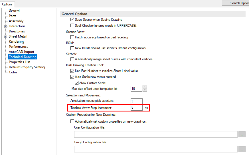
This new option allows designers and engineers to effortlessly manipulate text boxes within their drawings, enhancing precision and efficiency. With the simple use of arrow keys, users can now easily move text boxes in any desired direction, ensuring precise alignment and positioning. Additional control for the movement distance can be set in the Tools/Options/Technical Drawing.
Available in:
Enhanced ICD Shaded View Quality in Quick Views with Transparency
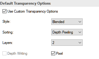
This new update enhances the ICD shaded view quality in Quick Views by adding transparency controls for quality and realism. Designers can now achieve a more comprehensive visualization of their models, improving clarity and accuracy during the design process especially when Transparency is set on parts. Multiple layers of Transparency can now be handled with options to control the visibility of each transparency level.
Available in:
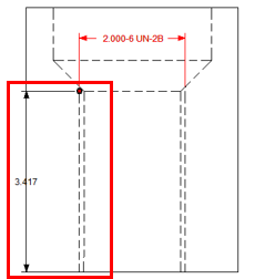
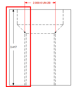
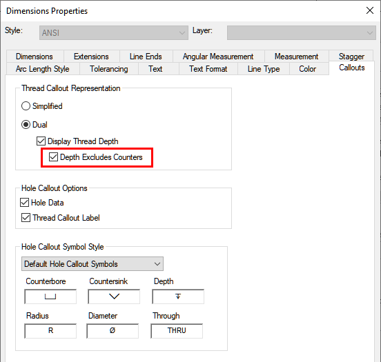
Cosmetic Threads Start Reference to the Starting Edge of the Hole
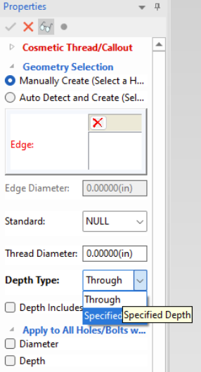
New options have been added to allow the thread depth to reference optional locations from the bottom of the counter area or to the top of the hole reference. This option can be stored in the styles of the dimension styles based on the information desired to call out on the Dual Thread Depth type. This can also be set in the Hole Tool or Cosmetic Thread tool in the 3D Scene for creation.
Available in:
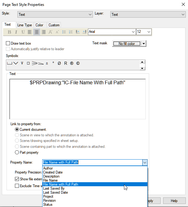
IronCAD Drawing New Text Property for “File Name with Full Path”
In the IronCAD Drawing Environment, a new option has been added for the File Name Text property to use the Full Path. This ensures that users are using the correct file information when reviewing the File Name in the Drawing.
Available in:
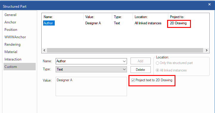
Project Custom Property Text to IronCAD Drawing
New options on the Part/Assembly Custom Properties to Automatically Project the Text string to the IronCAD Drawing. This option allows you to transfer critical information to the 2D Detailed document without having to manually type information or risk updating the information when the data in the 3D changes. This annotation can be relocated in the drawing once projected and the new location will be remembered in future updates. Using the ability, you can attach parametric string data to the custom property and get automatic dimensions (creation and updates) without manual intervention to recreate the callout information.
Available in:
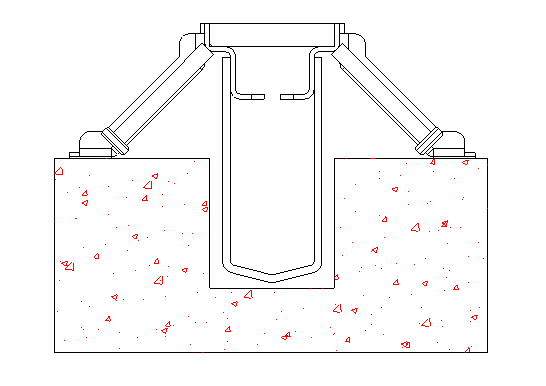
Support for Concrete Hatch Pattern Type
The hatch pattern styles have been updated on the IronCAD Templates to support a Concrete Hatch Pattern. For existing user templates, users can import one of the IronCAD Templates styles into the open template to copy the concrete hatch to this template.
Available in:
Modeling Enhancements
Structured Parts Enhancements
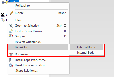
IronCAD introduces the ability for Structured Parts Bodies to Rename and Relink Breps. These features provide users with greater flexibility and efficiency in managing and organizing their designs while having the flexibility to change linked Breps or reconnect lost instances. Simply click twice on the body name to allow the renaming of the body to a user-specific text identifier. To relink an associated Body/Brep, right-click on the Brep in the scene browser to access the new option to link either internally or externally to another reference.
Available in:
TriBall Pattern of Pattern Support
Experience a new level of versatility with IronCAD’s support for a pattern of a pattern, leveraging the power of the TriBall pattern command to unlock unlimited design possibilities in your 3D models. This feature empowers designers and engineers to create complex and intricate patterns with unparalleled ease and flexibility. With the TriBall pattern command, users can now apply patterns to existing TriBall patterns that can be made up of Assemblies, Parts, and/or Features.
Available in:
Body Link Relationships Maintained Through Catalog Drop-In/Out Process
When creating linked bodies whether to internal objects or external objects, the link relationship generated will now be maintained when the owning object is placed into a catalog and reused in other scenes or in the same document. This powerful feature extends the possibility of designs by allowing reference geometry to be used in the construction of other parts.
Available in:
Prevent Dimension Flipping in Sketch and 3D Controls
When working in the Sketch and in 3D, users can create dimensions and angle constraints for geometry. However, when models are changed in typically large increments, the dimensions can solve correctly but can resolve in flipping the geometry to solve in a minimum move of the dimensions. This flipping result is often not desired. New options are available on certain dimension/constraint types.
For tangent constraints in the sketch, new options on the right-click of the tangent constraint for aligned and anti-aligned will be maintained through the solve.

For spline angle dimensions in the sketch, a new option to maintain angle direction to maintain the current angle side.
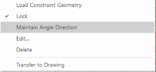
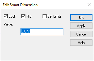
For general 3D Smart Dimensions, an option to flip is added to maintain the direction side of the dimension.
Available in:
Polyline Sketch Right-click or Double-Click End Creation
New improvements to speed up the polyline creation in the 2D Sketch have been added. During the polyline creation, simply right-click or double-click to end the current polyline command while still remaining in the tool. This allows the continuous creation of multiple polylines in the single polyline creation tool.
Available in:
2D Sketch to Convert Selected Connected Line Segment to Use as Construction
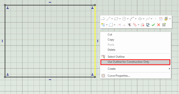
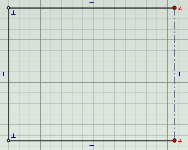
New behaviors have been added to the sketch to convert selected curves of a connected line segment to construction. Previously, the entire connected paths would be converted. In the new behavior, the selected curves are converted to construction curves and the endpoints will be disconnected. To maintain the connection, users can add coincident constraints to these points to maintain the connections. The behavior improves the speed at building reference and real geometry in the sketch.
Available in:
Equal Length Constraints in 2D Sketch Can Be Applied to Multiple Selections
New capabilities have been added to the Equal Length command to allow users to select multiple segments and apply the equal length constraint to the selection. The apply command will keep users in the command to allow for multiple sets of curves to be set to equal length. In addition, the command browser allows for selection and deselection in the scene (and double-click in the browser) to remove accidental selections.
Available in:
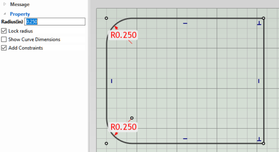
Fillet/Chamfer 2D Sketch Support Adding Constraints
The 2D Sketch Fillet/Chamfer tool now has the ability to add constraints when creating the fillet/chamfer. This setting is off by default along with the lock radius on the fillet to quickly add fillets/chamfers on multiple points with a user-set default value.
Available in:
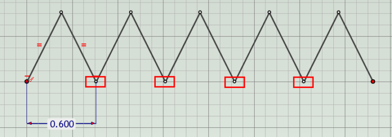
Automatic Merge of Points in a 2D Sketch Pattern
When patterning a selected set of curves that connect at points after the pattern, the points of the resulting pattern will automatically connect reducing manual work to connect them after the pattern command.

Available in:
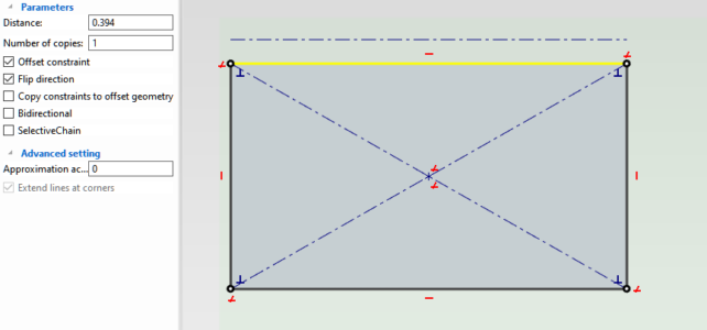
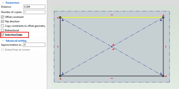
Offset Sketch Support of Single or Chain
The offset command has been enhanced to allow the offset of a single selected curve or the chain connected with the curve. This new option provides additional control in creating offset geometry when sketching.
Available in:
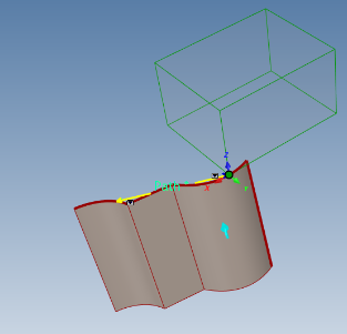
Path Constraint in Advance Positioning Constraints
The Path Constraint in the Advance Positioning Constraints has been enhanced to support multiple connected path segments. As long as the segments are connected, users can build a constraint to the path for the object to follow along.
Available in:
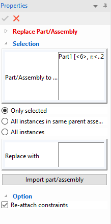
Replace Part/Assembly with Ability to Maintain Constraints
IronCAD’s new ability to replace parts and assemblies while maintaining constraints allows users to effortlessly adapt and evolve designs. This functionality empowers designers and engineers to update components within their designs without compromising the integrity of existing constraints. With IronCAD’s advanced Replace Part/Assembly capability, users can swap out components while preserving critical relationships and connections, eliminating the need to manually reapply constraints. This streamlines the design process, saves valuable time, and ensures accurate and reliable modifications.
Available in:
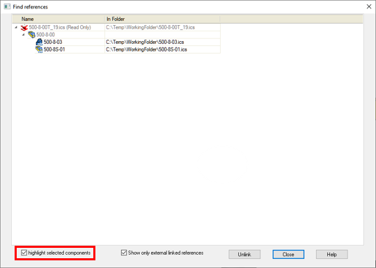
External Link Reference Dialog Improvements
The “Find Reference” command dialog for external/internal links has been improved to allow highlights when selecting the list of items. This helps users understand which link is connected to the selected list element.
Available in:
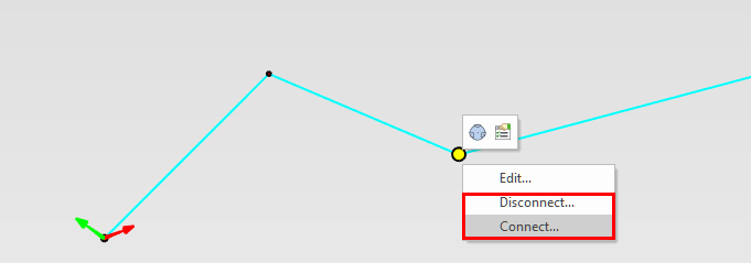
3D Curve Support for Connect/Disconnect Options on Right-Click
Similar to the 2D Sketch, the 3D Curve has adopted the ability to right-click on points and connect/disconnect the two joining curves. This is useful when creating 3D curves to have a connected segment after creating and modifying curves in the environment. To denote connected, the endpoint will be a small connection point while disconnected are larger endpoints.
Available in:
Sheet Metal Modeling Enhancements
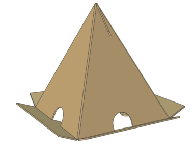
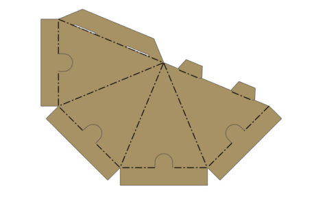
Sheet Metal Sketch Bend Support for Angles Less the 90 Degees for Cone Shape
In the Sheet Metal Sketch Bend, users can create multiple sketch lines to fold a sketch into a 3D model. New support for angles less than 90 degrees that could represent a cone-type shape in sheet metal. An example of this could be corrugated packaging type shapes.
Available in:
Sheet Metal Set Bend Support for Individually Set Angles
In the Set Bend Angle command, users were allowed to modify the bend angles in the Bend Feature section initially with all angles in the command using the same value. Improvements have been made to allow users to modify the sketch bend angles individually within the same set angle command/feature. This brings new capabilities to the command and improves the overall design process with fewer features needed.
Available in:
CAXA DRAFT 2D Drawing Improvements
Set 3D Info – Influenced by Open Scene Configuration
The “Set 3D Info” controls the information displayed in a Title Block. Whenever a View is Generated, this information is populated based on that last View inserted. Previously this information was influenced by the Configuration of the Open Scene, rather than strictly following the selections within “Set 3D Info”.
Available in:
Broken-Out Section – Editing is Affected by View Scale
The Boundary or Loop of Broken-Out Sections previously was affected by the View Scale. This has been removed to give the correct result in the Broken-Out Section.
Available in:
Broken-Out Section – Ignores Use Part Color Selection
Previous versions of the Broken-Out Section would ignore the Use Part Color setting on the views. This has been resolved so that the curves follow the part color settings.
Available in:
Editing the Extension of Break Lines
Break lines on a broken view can now be edited to adjust the length. By default, the extension goes to the view boundary. It is desirable to move these extensions when the views are large to make a more reasonable view for drawings.
Available in:
Collaboration and Translation Enhancements
Support for the Latest KeyShot 2023 Release
IronCAD now integrates seamlessly with the latest version of KeyShot (Version 2023), the renowned rendering and animation software. This integration enables users to effortlessly visualize and present their designs with unmatched realism and precision. Users can purchase new or perform a one-time upgrade to the latest version if they previously own the KeyShot for IronCAD product.
Available in:
Support for the Latest Translator Versions
IronCAD’s Native Translator has been updated for the formats listed below for formats such as SolidWorks, Inventor, Pro/E, Unigraphics, and Catia.
CATIA V5: V5R8 – V5–6R2023
Pro/E (CREO): 16 – Creo 9.0
UG NX: 11 – NX 2212
Inventor: V11 – V2023
SolidWorks: 98 – 2023
SolidEdge: V18 – SE 2023
JT Import: 8 – 10.2, 10.3, 10.5, 10.6, and 10.7, And Graphics Import
IFC: IFC2x3, IFC4
Rhino: V2-7
Available in:
ICAPI Support for Undo for Add-ons
The IronCAD Application Interface (ICAPI) has now been improved to allow undo operations for add-ins developed in IronCAD. This enhances the control for developers to build custom applications that support undo which is typical in IronCAD operations.
Available in:
Multiphysics for IronCAD
Multiphysics for IronCAD has been updated to the latest version. Details will be shared in a blog post for Multiphysics for IronCAD 2023.
Available in:
IronCAD Mechanical
Updates to the latest version of IronCAD Mechanical. Details will be shared in a blog post for IronCAD Mechanical 2023.
Available in:
