|
|
Aligned Section Views |
|
|
|
Use aligned section views to display cross-sections of existing standard, general, or broken views that are defined by aligning to a specified portion of the section line.
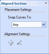
First select a current view on the drawing and then either select the Aligned Section View option on the View toolbar, from the View Types Ribbon Bar Group under the View Fluent Ribbon Bar, or select View from the Create menu and then choosing Aligned Section. Selecting this option activates the Aligned Section View command bar.

Aligned Section View Command Bar
The first step in the section line creation is to draw the desired section line using geometry from the 2D Drawing Tools toolbar on the Sketch Fluent Ribbon Bar. The section line can contain lines and arcs to form a single section line. Using arcs in the section line will create a non-sectioned region in the resulting section view. Once the section line is created, select View Alignment from the Aligned Section view Command Bar. Next, select the line segment, at either end of the section line, to be used as the alignment of the view. Use the Flip Sight Direction option to change the sight direction of the section. Last, select Place View and place the aligned section view on the drawing.
Multiple Aligned Section views can be placed on a single view. To edit section lines of an Aligned Section View, right-click on the view containing the section line and select Edit Aligned Section Line and then choose the desired section line defined in the menu. This will allow the user to edit the section line and the options defined like View Alignment and Sight Direction.
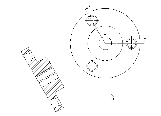
The following illustration demonstrates application of an aligned section line and the resulting section view.

Section line display and position can be edited by right-clicking the line and selecting Properties from the resulting pop-up menu. The following options are available:
-
Offset. In this field, enter a value to specify the distance the line should be repositioned from its origin. When you return to the drawing, selecting the Update All Views button on the View toolbar (or the Update All Views option from the Tools menu) applies the changes to the associated section view. Since section lines are associative, they will retain their reference points regardless of modifications applied to the parent view.
-
Style. From this field’s drop-down list, selected the desired section line style.
-
Layer. From this field’s drop-down list, select the desired layer to which the section line is assigned.
-
Arrows. Use the following options to define section line arrow display.
-
Points away from line (ANSI). (Default) Select this option to display section line arrows pointing toward the line.
-
Points toward the line (ISO). Select this option to display section line arrows pointing toward the line.
-
End offset. In this field, enter a value to specify the distance section line arrows should be offset from the line ends.
NOTE: To change the default properties for section line arrows, select the Default Properties button the Styles and Layers, select Section Lines from the list of elements, and then edit the properties, as desired.