Free 3D Configurations and Collaboration with IronCAD Compose
Jul 9, 2013
In June 1998 I would notice a blur periodically crossing my vision. I ignored it. Flash forward to 2013, and now I wish I’d paid attention to the IronCAD neXt Generation Design Collaboration Suite.
It’s no longer a half-conscious blur but a full-featured MCAD suite consisting of software elements for 3D design, 2D design and detailing, collaboration, configuration, and data translation. I’m paying attention now and I think you should, too. Here I’m going to tell you about one part of the suite, IronCAD Compose.
Out of the Box
IronCAD Compose is not a full-fledged MCAD package, but software for composing models from pre-drawn parts. It is a free download from IronCAD’s website. IronCAD Compose is a tessellated (faceted) viewer and so can import similar 3D file types, such as .obj, .stl, VMRL, and SketchUp, in addition to native IronCAD scenes. In terms of 2D, Compose imports .dwg and .dxf files along with IronCAD’s own formats .icd and .exb.
To get us started, Compose comes with 20 built-in catalogs. These are the parts with which we compose models. Many users, however, have removed these catalogs, and then added their own, creating an OEM version of Compose to send to customers or use as a sales tool.
For US$195, we can add the translator (IronCAD Compose-Trans) that imports additional file formats. The list includes neutral formats like ACIS, Parasolid, and STEP, as well as native files like CATIA, Pro/E, UG/NX, SolidWorks, and Inventor. This is probably the lowest-cost translator on the market. Considering the future partnerships with 3D content providers and the desire for interoperability, I consider Compose-Trans to be a necessary expense to expand the capabilities of Compose.
Getting Started: Understanding IronCAD
Although IronCAD Compose is a stand-alone application, the cool stuff happens when we start working with the designed-in intelligence of IronCAD models. To understand the Compose component, we first have some background on how IronCAD works. Because a previous article introduced us to a beginner’s view of IronCAD 2013, I’m going to explain additional methodologies of IronCAD.
IronCAD models in 3D. IronCAD has, of course, the customary 2D profile-and-extrude method comparable to other modelers, but why not design in 3D directly? By this, I mean that I select basic 3D shapes and then merge them together, brick by brick. These basic building blocks are both additive and subtractive, and are stored in the Catalog Browser: blocks, slabs, slots, cylinders, ellipses, spheres, pies, tori, cones, and more (see figure 1).
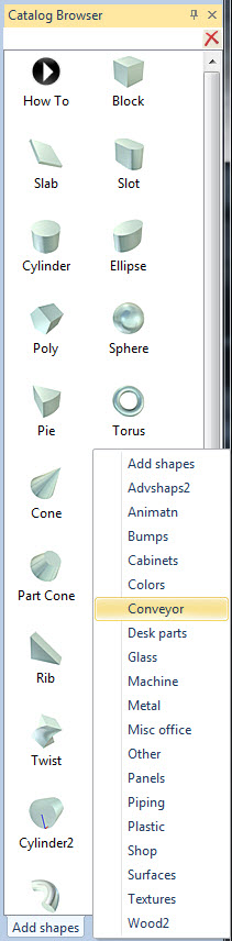
Figure 1: The many categories of IronCAD’s Catalog Browser
I drag the building blocks from the browser and locate them onto existing geometry – drag, snap, fit. After a building block is placed, I can adjust parametric values to fine-tune its shape and location, or else use dynamic editing tools to stretch, locate, and manipulate the geometry (see figure 2).
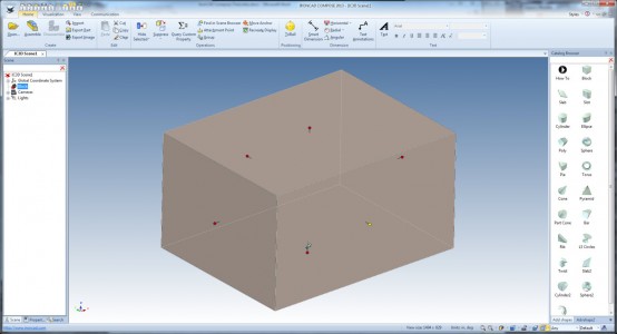
Figure 2: Dynamically editing a dragged-in block using control handles (the red push pins) and adding dimensions for parametric editing
The real power of Catalog Browser is not limited to me using it to build in 3D but comes in the ability to let me create a catalog from anything, including existing model libraries. Instead of dragging in just parts, I can drag entire assemblies and subassemblies into the design. This is because IronCAD is natively a multi-body CAD program, unlike typical solids modelers.
To build a part, drag in some geometry. Attach it to existing geometry as a feature of the same part; or drag it in as its own part. Drag in parts to build assemblies; drag in assemblies to create subassemblies. All this can be within the same file, which IronCAD refers to as a “scene.”
Let the Configuration Begin
Assuming I planned my project with configurations in mind, I can assign “attachment points” to geometry (see figure 3). These points are the key to the Compose software. When I bring geometry with attachment points from Catalog Browser into the scene, its points snap to existing geometry that also has attachment points. This means that geometry is automatically located and oriented, based on the rules defined earlier when creating attachment points.
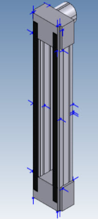
Figure 3: Example of attachment points, shown in blue
Consider this scenario: I’m a sales engineer working at a customer site with my laptop. IronCAD Compose is installed and loaded with my custom catalog. An intelligent model with attachment points has been created in IronCAD, and the scenes have been added to Catalog Browser. The customer wants to see how my product can be configured to fit his needs.
I begin by dragging in major subassemblies from Catalog Browser. I expend no effort in trying to assemble the components as they simply snap into place, based on the locations of the pre-assigned attachment points (see figure 4).
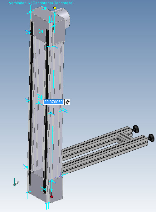
4: Rail with stand attached: dynamically edit the rail length or type in a value
But geometry is not the only aspect of Compose’s configuration powers. Components within the Catalog Browser can be linked to database with information like pricing, vendors, standard lead times, and other information important to the design department and the rest of the enterprise. For instance, when the Sales Engineer configures a new layout for a customer, he is determining price and lead time for delivery automatically. (Note that this would require customization to connect to customer’s systems.)
(IronCAD created demonstration videos to go along with each catalog, and you can view the video for the above example here http://www.youtube.com/watch?v=wN51T6Ef8qA.)
Third-Party Catalogs
Most MCAD vendors have their list of gold star partners who develop add-ons or extensions that integrate seamlessly within the software. Browsing IronCAD’s website, I found it under Products – Solution partners: https://www.ironcad.com/solution-partners.
Also, I have it on good authority that a growing consortium of partners is being established, with companies such as Traceparts and Cadenas Part Solutions already having a direct link in the software, and Traceparts being added to IRONCAD 2014. GrabCAD has also been added. Imagine being able to build custom configurations using off-the-shelf components that simply snap into place and include all pricing information. Applying IronCAD’s unique attachment points to neutral CAD data would be a significant development challenge, but I can see a substantial benefit for users.
In addition to configuring existing geometry, IronCAD Compose renders and animates scenes as well. Don’t just assemble new configurations for customers; show them off in full life-like representation, and watch as the model comes to life!
To sum up, for the amazing cost of free, IronCAD Compose comes with a faceted geometry importer, a 2D drawing importer, 3D PDF creator, twenty catalogs full of various amounts of pre-built geometry with the ability to customize more, a rendering engine, and an animation engine. And for an extra $195, it gains the ability to import neutral and native file formats.
What the Future Holds
Obviously no software vendor rests on its laurels, and IronCAD Compose is no different. I had the luxury of hearing from the IronCAD folks about a few of the highlights they plan for future development.
Which software review today is complete without mentioning the cloud? Traveling with laptops has become passé, and road warriors now are using Android and iPad tablets. Sometime in the foreseeable future, IronCAD Compose will be made available for tablets, with catalogs available through the cloud. Updates will be done real-time by the home office, and new configurations will be sent from the customer’s site to the engineering department before the sales engineer even gets around to filling out his expense report.
How about non-standard components? In my example, I stretched a component to meet the customer’s requirements; but what if the new length is not manufacturable? Someone on the design team has to verify the final configuration, before the sales order is signed.
The configured results can be brought into IRONCAD and turned into a real CAD model (as a b-rep) automatically. This allows salespersons to send the final product configurations to designers and turn them into a real CAD design, which makes it easily ready for manufacturing.
What if the sales engineer didn’t even need to travel. Consider the scenario in which the customer download pre-defined configurations from the internet, “redlines” it with his requests, and then sends it back to the manufacturer to negotiate the design. They should be able to do this real-time, using IronCAD Compose, on the cloud.
Conclusion
IronCAD Compose comes at an astonishing price ($0) in which we get 2D and 3D viewing, geometry configuration and manipulation, and rendering and animation. The software seems incomplete without the extra $195 for additional translators. Even though some CAD companies don’t charge extra for translators, most do due to the licensing cost.
While IronCAD Compose seems best fitted for the front-end of the design or sales cycle, I’d like to see it move towards the back end, as well. I could see me taking an end-item design, and allowing the manufacturing engineering and production planning departments to configure components to match the work cells or make-buy conditions. The potential is there, and the vision for Compose is one worth keeping our eyes on.
Writing this review was not the first time I heard about IronCAD, but it was the first time I gave it serious thought. IronCAD Compose turned out to be an amazing product for the front-end design, or for the sales cycle. I’m sorry I ignored this hidden gem of a CAD company for so long!
About the Author
Scott Wertel is a Configuration Manager in the defense and aerospace industry and provides freelance design services to a variety of interests. Scott has spent decades following the engineering software industry due to his “unnatural affinity” for CAD and uses that insight to best position his employer and clients for change. Scott graduated from the Milwaukee School of Engineering and is a licensed professional mechanical engineer in the state of Arizona.
Article reprinted by permission from CAD Digest