What’s New in IronCAD Design Collaboration Suite 2024!
Dec 20, 2023 |
IronCAD 2024 boasts a major step forward in productivity, flexibility, and versatility in mechanical CAD design. New features have been specifically added to aid users in mechanical machinery manufacturing and design, metal fabrication design, assembly layout/design, modular design, packaging design, and down to furniture design markets.
Key features expand across the 3D Design, including Innovative and Structured Design, Sheet Metal Design, Detailed Drawing and 2D Mechanical Drawing Environments, and Collaboration in Import/Export, Viewing, and Design Sharing.
Below are the key features included in IronCAD 2024:
IronCAD 2024 New Features
3D Design Environment Including Innovative and Structured Design
Link Part Tool (for Existing Scenes and Drag & Drop Actions from Catalog)
Support for External Links Using Different Configurations in the Same Scene
Copy as Linked Body Support (More Access Support on TriBall)
Replace Feature from Catalog (Extension of Replace Part/Assembly/Sketch)
Rotational/Display Performance (H-Dynamic Assist)
Dimensions Added on Part/Assembly Drop
Sketch Level Parameter Referencing During Smart Dimension Creation
Insert Scene Level Linking – Ask to Link to the Scene or Specific Part/Assembly
Excel Controlled Parameters and Configurations
Gear Constraints (Positioning Constraints Advance)
Attachment Point Editing (List All Attachment Points and Select Editing)
Ctrl-Alt Selection List Updated with Filter Selection
Smart Assembly Attachment Enhancement on Copy/Move of Connected Pairs
TriBall Dimension Creation for Parts (to Anchor)
Custom Property Support for Scene Browser Tree Names and File Names when Saving
Body Property BOM and Bodies Included for BOM Settings
Enhanced Structural Steel Weldments for Gussets and End Caps
Structured Frame Edit Profile and Find Profile
Top-Down Skeleton Design Approach Improvements
Assembly Pattern Tool (Similar to Pattern Feature)
Extrude Feature To Face/Surface Support for Datum Planes
View Constraint Relations New Improvements in Visualization
3D Curve Improvements such as Hide Curves and Curves Parallel to Datum Constraint
Sheet Metal Modeling Improvements
Unfold Remember Add Stock to Account for Extra Material
Solid to Sheet Metal Support Miter with Cut Sketch and Rip Edges
Rapid Sheet Metal Quotation Tool
Cross Break and Cut Line Support for Layer/Linetype in IronCAD Drawing
Sheet Metal Tables for Bend Deduction and Bend Coefficient
Improvements to the Set Bend Tool for Sketch Bend Individual Bend Settings
Support New Property Type $PRPDrawing:”IC-SMThickness” in ICD
Controls to Automatically Set Assemblies, Parts, and Features to Specific Layers and Line Types
Ability to Individually Shaded Selected Parts in Drawing Views
Enhancements to Bulk View Automated Drawing Creation
Introducing the Projection View Standard View Type
Alignment for Break Lines End in Broken Views
Improving Performance through Embedded Image and PDF Saving
ICD Property Browser now supports Unicode Symbols
Use Zero-Width Line when Exporting from the ICD drawing to PDF format
CAXA DRAFT 2D Mechanical CAD Drawing Improvements
Create a Drawing from Selected in the Scene Using CAXA DRAFT
Section View Depth Setting Added to CAXA Draft
Generated Views – Shaded – Support Hide Assemblies
Multi-Frame/Paper Drawing Support
New Grouping Command to Group/Ungroup Selected Elements
Polyline Selected Point Display Improvement
Multi-Level Block Explode Function
Curve Array Option to Keep or Delete Source Objects
Switch Direction During Arc/Elliptical Creation with CTRL Key
Cloud Line Tool Support for Freehand, Rectangle, Polygon, and Convert Line/Circle/Arcs
Polyline Edit Join Function Improved to Connect Closed Polylines
Create Points and Splines from Clipboard Copied Data
Recreating Boundary Function During Editing
Support for Auto Layer Rule for Center Lines
Rotate Symbol Annotation Support for Text Height Setting
Paste as Plain Text During Text Creation/Edit Function
Explode Attributes Function for Blocks
Item Number Splitting Support for Continous Split
BOM Editing Part Number Reoder and Move To Top/Bottom
BOM Export Function Support for Output Hidden Items
Improvements in the Library Functionality
Design Center List/Thumbnail Display Functionality
Support for Editing OLE Objects Created in Other CAD Software
Support for Copy/Paste of CAD Data to and from Other Software (Such as AutoCAD)
Printing Support for Printable Areas (Margin Settings)
Smart Plot Support for Multiple Page Plot to Single PDF
PDF Import Supports Multiple Page Import
Improvements in Print Output to Images
Insert Image Support for Handle Uniform Scaling and Clip Boundary
File Comparison Improvements for Comparison of Geometrical Data in DWG
New Layout Switching Function with CTAB Command
Dynamic Input Hover Display of Information for Grip Points
Search Command Added to Customization Keyboard Functionality
System Options Added to Command Line Commands
Collaboration in Import/Export, Viewing, Rendering, and Design Sharing
IronCAD Native Translator, support for the latest file types
New IronCAD Native Translator BIM (Coming Q1 2024)
Open the 3D Scene as “Lightweight” (facet data only) for Viewing
KeyShot for IronCAD Improvements
Search for Commands Expanded Search to Help System and Related Topics
Synergy Collaboration Platform
3D Design Environment Including Innovative and Structured Design
Link Part Tool (for Existing Scenes and Drag & Drop Actions from Catalog)
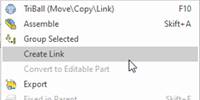
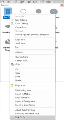
Exciting enhancements have been introduced to elevate the already powerful IronCAD Catalog Drag & Drop design capabilities within a single 3D scene file. Options have been added to catalog Parts/Assemblies in the Right-Click menu to Link on Drop. Activating the Link on Drop will automatically create new link references when the part or assembly is dropped multiple times into the scene.
In addition, you can now select multiple objects in the scene and Create a Link from the selection. This can also be done with the Search Browser, where you can search and use the Select Results to automatically link similar objects.
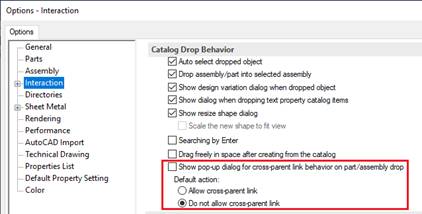
There are options for cross-parent linking, controlled in the tools/options, to allow this linking to occur if desired.
This innovative improvement isn’t just about convenience – it significantly enhances your overall design performance. By reducing file size and the scene structure through the creation of linked instances for parts and assemblies, it marks a substantial leap forward in optimizing your design workflow.
Support for External Links Using Different Configurations in the Same Scene
Introducing enhanced controls for the Insert Part/Assembly command! Now, you have the flexibility to opt for either the complete tree structure (Standard, maintaining the current behavior) or the Limited Reference (Limited) option. The Limited Reference feature empowers you to effortlessly change the active configuration and accommodate multiple different configurations of an Externally Linked file within the 3D Scene. This exciting update opens up new opportunities in your designs, providing greater flexibility and efficiency in reusing external references.
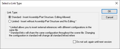
Standard is the default and has the same behavior as previous versions, where the external linked file can only have the same configuration for all instances inserted within the document.
Limited restricts the contents of the scene browser tree structure to only showing the icon of the selected component (Part/Assembly) but allows you to choose different configurations on each instance of the externally linked file.
Copy as Linked Body Support (More Access Support on TriBall)
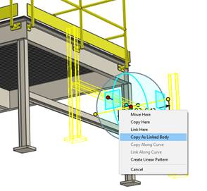
The already powerful Copy as Linked Body feature, initially available on the TriBall Mirror command, has now been expanded to encompass most Copy/Link operations on the TriBall. This enhancement empowers users with a versatile tool to create links to geometry within scenes while allowing for easy modification of these links with subtle variations such as color adjustments or the addition of unique features.
Imagine having similar parts with different material settings, as an example. With this upgraded functionality, you can effortlessly create these distinctions while preserving the underlying geometry. This not only adds a new layer of flexibility to your designs but also streamlines the process of maintaining consistency across various elements.
Replace Feature from Catalog (Extension of Replace Part/Assembly/Sketch)
Building upon the familiar Replace Part/Assembly/Sketch Feature from IronCAD’s Catalogs (CTRL-Drag and Drop), we’re thrilled to announce that this capability has now been extended to Features. Users can now leverage Catalogs to construct libraries of features, seamlessly replacing existing feature geometry on parts and assemblies.
This enhancement provides users with a powerful tool to explore different variations and refine designs swiftly, perfectly aligning with customer change requirements. The expanded functionality not only streamlines the replacement process but also adds a new dimension to design exploration and iteration. Dive in and experience the enhanced flexibility and efficiency that this feature brings to your design workflow!
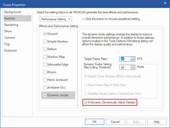
Rotational/Display Performance (H-Dynamic Assist)
Significant performance improvements have been implemented in dynamic rotation within the 3D environment, thanks to the introduction of the new H-Dynamic Assist. This option has been specifically designed to elevate the overall rotation display, ensuring smooth and seamless rotations even when dealing with large assembly data.
The H-Dynamic Assist brings a new level of efficiency making it easier for users to navigate and interact with their designs. With reduced lag and minimal display reduction on edges and faces during rotations, this improvement promises a smoother and more enjoyable experience.
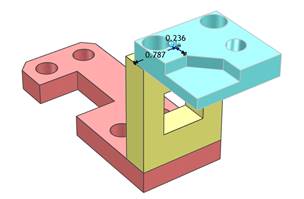
Dimensions Added on Part/Assembly Drop
A new setting under Options, Interaction can now control dimension creation for parts/assemblies when dropped onto the faces of other parts/assemblies. This allows for fast positioning of the dropped part/assembly. The dimension will be created from the anchor of the dropped part/assembly to the nearest edge of the landing part/assembly. With this, users can place the anchor at an appropriate location that will aid in the dropping location and allow for quick positional adjustments with the dimensions.

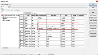
Text-Based Parameter Support
The parameter table has been improved to accommodate text-based parameters, enabling the use of more intricate parameters and expressions. This enhancement allows users to create formulas based on text rules, such as “If text equals text, use one value; otherwise, use another value.” For instance, users can now employ expressions like “IF( (Length < 4 inches), Value A, Value B)” to define expressions and values within the parameter table.
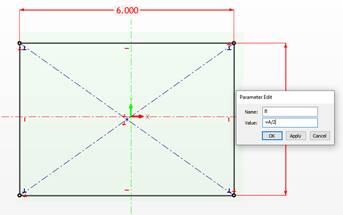
Sketch Level Parameter Referencing During Smart Dimension Creation
When creating dimension constraints in the 2D Sketch, users can now directly refer to other dimensions/parameters to return a value or to create parametric expressions. To refer to another parameter, enter =parameter name in the value field of the dimension to create the expression on the new dimension. To refer to another dimension’s value, directly select the desired dimension in the sketch (Left-click) to obtain its value while the Value field is active. This new capability can reduce errors in acquiring values and can improve parametric creation by creating the expressions in place.
Insert Scene Level Linking – Ask to Link to the Scene or Specific Part/Assembly
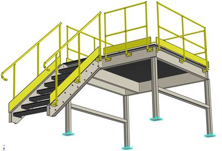
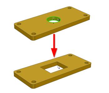
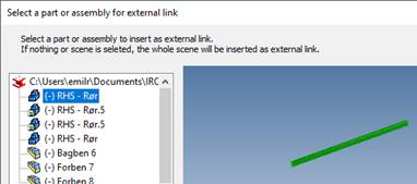
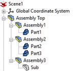
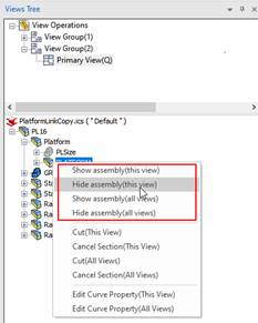
When you insert another ICS into another file as a link, there are different behaviors on how the inserted file will be displayed depending on the scene browser tree structure in the file. When there is a single element (like a part or assembly), the insert as link will create a link to that specific part or assembly. If there are multiple objects at the top level (see image below), IronCAD creates a new assembly container to group these elements into and create a link to the actual ICS scene document.
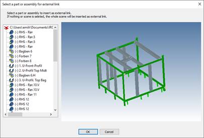
This assembly container can cause confusion and creates a special element that the user may not want. Now during the Insert as Link, you can select the desired part/assembly to have the link attached to only that specified element.
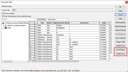
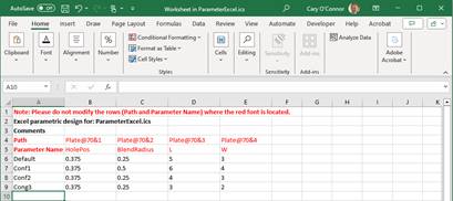
Excel Controlled Parameters and Configurations
New Excel Linked Parameters and Configurations have been added to IronCAD’s parameter table. Inside the Parameter Table, selecting the Excel Design will launch Excel and allow you to choose the parameters for building Configurations based on Parameters. Users can create multiple rows with different configuration names. Clicking back on Excel Design after creating the rows will close Excel and return to IronCAD. This will create configurations in IronCAD that allow you to toggle various configurations where the parameters will update and apply. Excel Design allows users to drive geometry by different configurations for desired design scenarios.
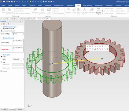
Gear Constraints (Positioning Constraints Advance)
New advance constraints for Gear Constraints have been added. This constraint allows users to define the teeth or ratio of the gears that will be used when the gears are rotated. Use the TriBall to visually rotate one gear and the other gear will update based on the constraint. Use the Mechanism Mode to dynamically rotate and enable collision detection to verify fit.
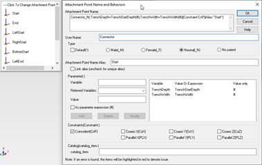
Attachment Point Editing (List All Attachment Points and Select Editing)
The Attachment Point Editor has new abilities to show all the available attachment points on a selected part/assembly when activated using the Ctrl-Alt-Left-Click activation. The new UI allows you to edit multiple attachment points in one dialog with the user interface highlighting the attachment point currently being edited.
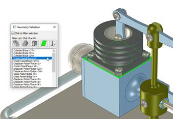
Ctrl-Alt Selection List Updated with Filter Selection
The Geometry Selection List activated by selecting Ctrl-Alt and Left-Clicking has been updated to offer a filter selection where you choose which elements to see in the result list. This also has been improved to select Attachment points (and launch the Attachment Point Editor).
Smart Assembly Attachment Enhancement on Copy/Move of Connected Pairs
Improvements have been made on connected pairs of parts/assemblies using Attachment Points (Smart eBehaviors). Selecting the paired components and using the TriBall to Move/Copy will retain the attachment point connections. This also applies if the paired component is placed in a catalog and dropped out into the scene or a new scene.
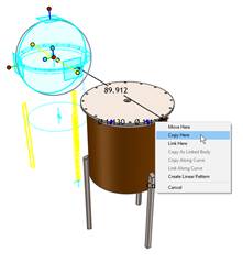
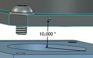
TriBall Dimension Creation for Parts (to Anchor)
When using the TriBall Edit Distance from Point, you can choose to create a Smart Dimension between the object and the reference surface at the same time. This dimension will be created to the reference face/edge and to the anchor of the selected part/assembly used in the operation. Using this capability, users can quickly add reference dimensions on the fly to enable faster adjustments later for the positioning of objects.
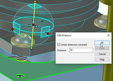
Edit the Smart Dimension measurement afterward by selecting the part.
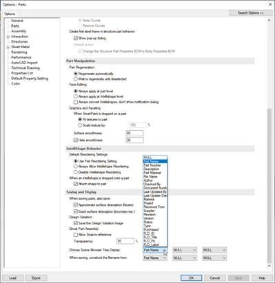
Custom Property Support for Scene Browser Tree Names and File Names when Saving
The Tools/Options/Parts ability to set the Scene Browser Tree Display and File Name now supports custom properties. This gives more control to defining the display and name of parts/assemblies (and files). Custom Properties allow for more advanced values that can be basic text or text extracted by formulas.
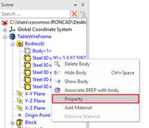
Body Properties Access
In Structured Parts, models can have multiple bodies that are used to build the desired part which is common for structured frames. Users can now right-click on the bodies in the scene browser and edit the properties to apply name, part number, description, and material information.
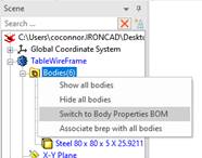
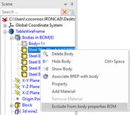
Body Property BOM and Bodies Included for BOM Settings
In Structured Parts, new options are available to set the behavior of the Part BOM to be based on the part or based on the Bodies. Based on the Part Properties, the BOM will return a single BOM row for the part based on the part property information. Based on the Body Properties, the BOM will return a row for each body in the body folder using the properties set on each body that is set to be included in BOM. Right-click on the BodiesFolder to select the desired BOM type. Also, users can right-click on individual bodies to include or exclude from the Body Property BOM.
Enhanced Structural Steel Weldments for Gussets and End Caps
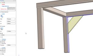
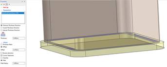
New elements, Gussets and End Caps have been added to the Structured Frames in Structured Parts. Gussets are structural reinforcements used to strengthen the connections between two or more components such as structured frame members. End Caps are used at the end of frame members to cap or close the members. Gussets are created between two face references and have options for the profile type and chamfer settings. End Caps are constructed from the selected face reference with options for the size, offset, and corner treatments.
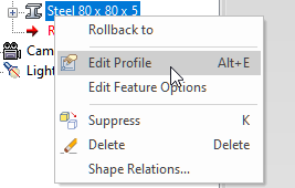
Structured Frame Edit Profile and Find Profile
Structured Frames now support the ability to Edit the Profile of standard frame members. Editing the profile allows users to add reference geometry (such as points) that can be used in other operations like setting the section reference direction. During the Edit Feature command, users can also select Find Profile to be taken directly to the frame members defining profile location.
Top-Down Skeleton Design Approach Improvements
Improvements have been made in IronCAD 2024 to allow for a Top-Down Skeleton Design approach. Users can create empty assembly containers in the scene browser and add parts and sub-assemblies to build the design structure. Empty parts can also be created and activated later when adding the geometry information.
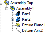
Assembly Datum Plane Support
Assemblies can now contain Assembly Datum References such as Plane, Axis, and Point. Select the assembly and then select the desired reference type under the Structure Parts Ribbon Bar.
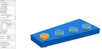
Assembly Pattern Tool (Similar to Pattern Feature)
A new Assembly Pattern Tool has been added to create patterns of parts and assemblies using Linear, Bilinear, Circular, Edge, and Sketch patterns. The advantage of this tool is that you can establish references to edges for directions that will update when these references are modified.
Extrude Feature To Face/Surface Support for Datum Planes
The Extrude To Face/Surface in the Extrude Feature now supports selecting Datum Planes as the reference in this command. This offers more flexibility and more complex relation support when working with structured parts.

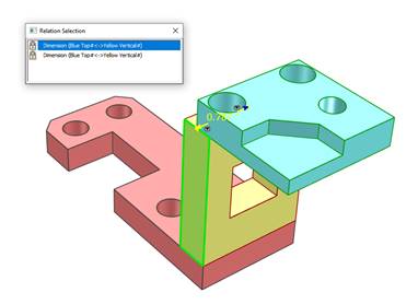
View Constraint Relations New Improvements in Visualization
The View Relations function used to highlight dimensional relations on a selected part/assembly offers new visualization improvements. Now users can choose the desired relation and the interface will highlight the relation in the 3D environment. Users can directly right-click in the dialog to access the options that are available for the selected relation.
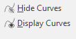
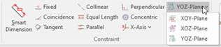
3D Curve Improvements such as Hide Curves and Curves Parallel to Datum Constraint
New commands have been added to the 3D Curve tool for Hide/Display curves and to create constraints parallel to the XY, XZ, and YZ planes. The Hide Curves allows users to select individual curve segments to hide. The Plane Constraints allow users to select a curve and make it parallel to the selected plane type.
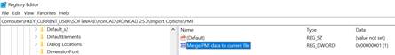
PMI Saved to Catalog Item
3D PMI added to parts and assemblies in the scene can now be added to catalogs for use in other documents. This option is controlled by a registry setting to enable when needed. Note: The 3D viewing orientation needs to be the same when dropped out from the catalog to maintain the identical look of the annotations.
Sheet Metal Modeling Improvements
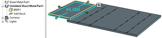
Unfold Remember Add Stock to Account for Extra Material
In Sheet Metal Unfolded parts, you can now add additional stock material (Add Stock) to account for extra material needed for manufacturing such as lofted or rolled material. Add stock added will be associated to the unfold stock. When modifications are made in the folded, the unfold and added stock will update to reflect these changes.
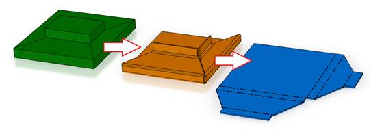
Solid to Sheet Metal Support Miter with Cut Sketch and Rip Edges
The Solid to Sheet Metal Tool has been improved to allow for mitered geometry. Using rip edges and a sketch/3D Cuves as Cuts, users can define how a solid needs to be split for the miter and the gap size for the rips. Add 2D Sketches for example that have lines that define the split. During the Solid to Sheet Metal Tool, select this sketch and lines to create the cutting.
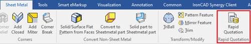
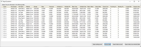
Rapid Sheet Metal Quotation Tool
A new tool for a Rapid Sheet Metal Quote has been added. Select single or multiple sheet metal parts and run the tool to generate a table that can be outputted containing relevant information for quotations from fabricators.
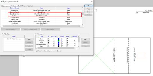
Cross Break and Cut Line Support for Layer/Linetype in IronCAD Drawing
The Cross Break and Cut Lines added in Sketch Bends can now be set to different line types and layers in the ICD. In the Style and Layer Tool, new element options have been added to allow for different styles for these elements. Note: For drawing views that you want to enable this layer and line type assignment, users will need to enable it in the view properties.
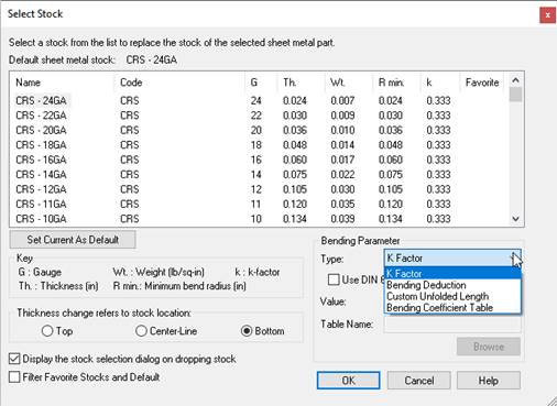
Sheet Metal Tables for Bend Deduction and Bend Coefficient
In the Select Stock and Stock Properties, users can select a Bend Deduction and Bend Coefficient that loads a table of available settings for a given thickness/radius of a sheet metal part.
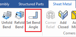
Improvements to the Set Bend Tool for Sketch Bend Individual Bend Settings
With the Set Bend Tool, you can add different angles to override the bend’s set angle. The tool has been enhanced to work with Sketch Bends and individual bends of a single sketch bend shape. With the Individual bend selection, users can select various bends of a sketched bend to set the angle.
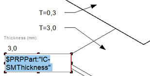
Support New Property Type $PRPDrawing:”IC-SMThickness” in ICD
Display the thickness of sheet metal via a new text box property in the IronCAD Drawing. Simply add a text and use the new property to access the Sheet Metal thickness value in the text field.
2D Detail Drawing (ICD)
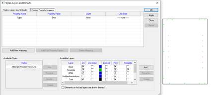
Controls to Automatically Set Assemblies, Parts, and Features to Specific Layers and Line Types
Often, you may want to have specific parts/assemblies/features appear on different layers or with different line types to denote objects or to be used in exporting to DWG/DXF for manufacturing processes. IronCAD 2024 allows users to define Custom Property attributes on parts/assemblies/features in the 3D where these properties can be used to specify custom mapping for layers and line styles.
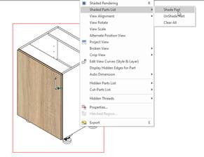
Ability to Individually Shaded Selected Parts in Drawing Views
New capabilities have been added to allow individual parts to be shaded in the drawing view. Quick views are the only view type that supports this option and when activating this command, it will automatically ask users if they want to switch to a quick view type.
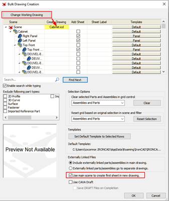
Enhancements to Bulk View Automated Drawing Creation
One of IronCAD’s most powerful automation tools is the Bulk View Creation. IronCAD 2024 continues to improve the usability of this tool by adding options to use the main scene assembly for the first view creation and the option to change the source saved ICD.
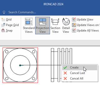
Introducing the Projection View Standard View Type
A new view creation type has been added to IronCAD 2024. The Projection View allows users to select existing views and create a projection view based on the direction pulled from the view (45 and 90-degree increments). This is useful to get the desired orientation of views to create annotation and documentation.
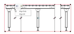
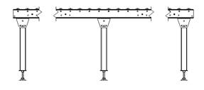
Alignment for Break Lines End in Broken Views
New options have been added on the endpoints of Broken View Lines to allow for alignment options. Users can choose to Align All to align both sides of the broken view lines or align just one side of the line ends. This is a useful tool to quickly adjust the broken line ends and zig-zags and have everything aligned.
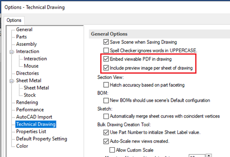
Improving Performance through Embedded Image and PDF Saving
New Tools-Option-Technical Drawing settings have been added to enhance the saving and file size of ICD’s. IronCAD by default, saves a viewable PDF inside the file document that can be accessed on file systems by right-clicking the ICD and selecting view. Users can turn this off to improve the document saving time and the file size. Similarly, users can choose to save thumbnails for each sheet of the ICD. With this option off, the file size will be greatly reduced.
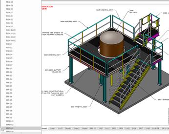
Sheet Tab Selector
In many cases, drawings may contain several sheets where it is difficult to browse to the desired sheet. Now users can Ctrl-Left-Click on the scroll arrows to bring up a list of all the sheets. Using the mouse scroll wheel, users can quickly scroll to the desired sheet.
ICD Property Browser now supports Unicode Symbols
The IronCAD Drawing Property Browser now supports Unicode symbols in the Symbols Pallete used in dimensioning.
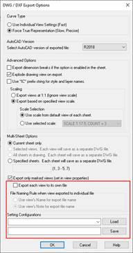
Improved DWG/DXF Export Settings: Individual View Export, Save Settings, Name Based on Customizable Note, and Real Arc/Circle Export for DRAFT views
New options have been added to the IronCAD Drawing Export to DWG/DXG settings.
·Individual View Export – This new option allows individual views to be exported directly to DWG/DXF. Using the Marked View for Export Setting, these views will each be exported individually.
·Export Filename Based on Note – Combined with the Individual View Export, users can have the name of the files generated based on the Note in the view properties. This is powerful since users can use custom property mapping to construct a note.
·Save Settings Controls – New controls have been added to save the setting in the export dialog. Simply save and recall the desired setting for the particular export task. By default, the last used setting defaults when opening the export dialog.
·Draft-Based Export of True Arcs/Circles – Draft views have been enhanced to export true arcs/circles when exporting to DWG/DXF. This reduces the need for precise geometry exporting which can take longer to generate during the export process. Note: Splines will still be exported as facetted geometry.
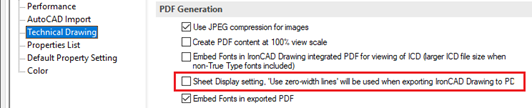
Use Zero-Width Line when Exporting from the ICD drawing to PDF format
New options in the Tools-Options-Technical drawing have been added to turn on/off the Zero-Width Line display when exporting to PDF. It is useful to have exported PDF’s with the accurate line width settings.
CAXA DRAFT 2D Mechanical CAD Drawing Improvements
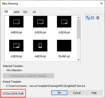
Create a Drawing from Selected in the Scene Using CAXA DRAFT
The Create Drawing from Selected in the 3D Scene Environment has been improved to support the creation of CAXA DRAFT drawings. Simply right-click on parts/assemblies and select Create Drawing from Selected in the resulting pop-up menu. In the dialog, select Use CAXA Draft.
Section View Depth Setting Added to CAXA Draft
The section view command has been enhanced to support section to a specified depth. In the Section Command Bar, you can set a depth by input or by drag and drop sizing.
![]()
Generated Views – Shaded – Support Hide Assemblies
Shaded Quick Views in CAXA DRAFT now correctly support the Hide Command found in the Views Tree on assemblies located inside the view.
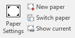
Multi-Frame/Paper Drawing Support
New in CAXA DRAFT is the support for Multi-Frame Papers. With this new capability, users can create multiple paper frames in the model space and activate a selected paper to work on. This opens new capabilities in creating drawing documents within CAXA DRAFT. When the paper is active, you can make use of commands like BOM’s that can exist on each paper with Item Bubbles determined by the active paper.
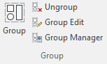
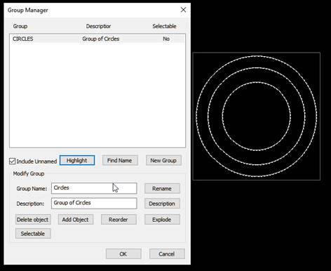
New Grouping Command to Group/Ungroup Selected Elements
A new Group Command to create a group of selected curve elements. Each group can be managed by the Group Manager to define a name and description. Operations such as move, copy, rotate, and modification like scale are available on the groups.
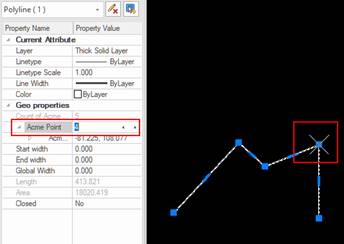
Polyline Selected Point Display Improvement
In the properties panel on a selected polyline, users are able to toggle through each point of the polyline. When doing this, the points will be highlighted to identify the current point being selected/edited.
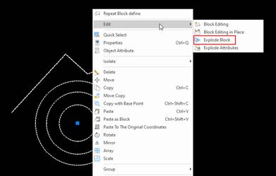
Multi-Level Block Explode Function
Blocks now have the ability to explode which will explode all levels of the block. Even if the block is a multi-level block, the explode will flatten the entire block contents.
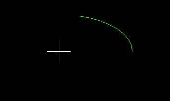
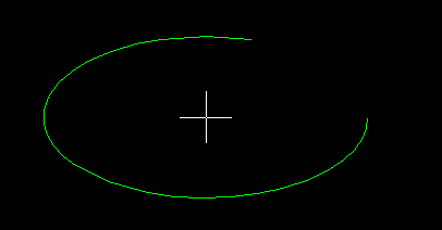
Curve Array Option to Keep or Delete Source Objects
When using the Array tool and selecting the Curve Array type, the user has the option to maintain the source object or delete the source object.
![]()
Switch Direction During Arc/Elliptical Creation with CTRL Key
During the creation of Arcs and Elliptical arcs, users can hold down the Ctrl Key and move the mouse to change/flip the direction of the arc.
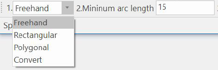
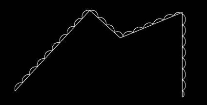
Cloud Line Tool Support for Freehand, Rectangle, Polygon, and Convert Line/Circle/Arcs
The Cloud Line Tool now supports additional creation types such as Freehand, Rectangular, Polygon, and Convert (from a selected set of connected curves from lines, polylines, circles and arcs). During the creation of the Convert, users can select to keep or delete the source curves.
Polyline Edit Join Function Improved to Connect Closed Polylines
When editing polylines with the Polyline Edit command, support for joining selected curves that are connected at both ends into complete polylines, improving the efficiency of merging complex shapes.
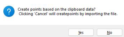
Create Points and Splines from Clipboard Copied Data
Support for importing data stored in the clipboard or a file when drawing points or splines.
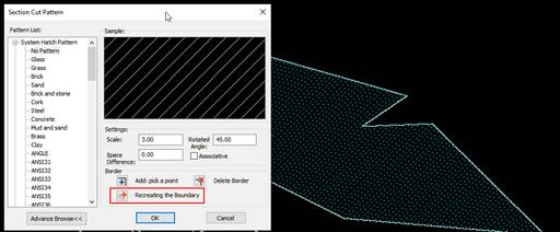
Recreating Boundary Function During Editing
When double-clicking to edit hatch lines, gradient files, or fill objects, a new option to recreate boundaries is available. This command will recreate the boundary based on the hatch/fill size.
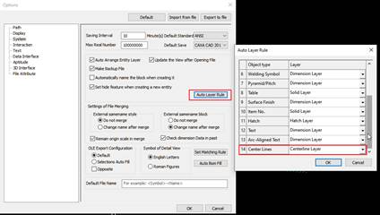
Support for Auto Layer Rule for Center Lines
The Auto Layer Rules now support setting the Layer information for Center Lines.
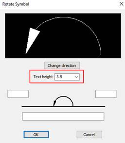
Rotate Symbol Annotation Support for Text Height Setting
In previous versions, the Rotate SymbolAnnotation set the Text Height in the Style. Now this can be set individually during the command.
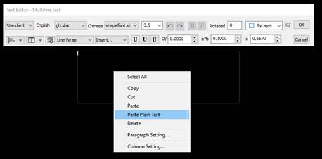
Paste as Plain Text During Text Creation/Edit Function
When working with the Text Editor, you can now Paste as Plain Text from other sources of copied text.
Explode Attributes Function for Blocks
New options in the Block Editing to Explode Attributes have been added. This command will explode the block and convert the attribute to text elements.

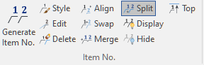
Item Number Splitting Support for Continous Split
In the Item Number Split Command, users can select to have a continuous split or a separate split.
![]()
BOM Editing Part Number Reoder and Move To Top/Bottom
When editing the BOM, new behaviors have been added for Moving items with a Move to Top/Bottom. Also, a new Reorder Part No. option has been added that can reorder after rows have been moved (reorder from 1 to X or reset).
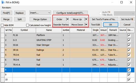
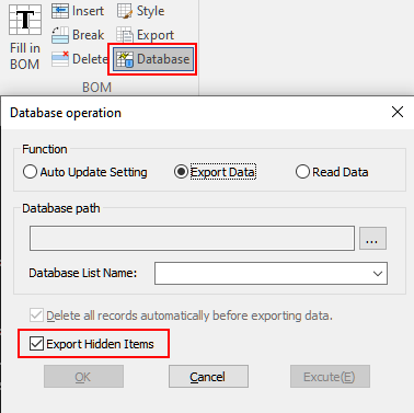
BOM Export Function Support for Output Hidden Items
Using the Database BOM tool and selecting Export Data, users now have options to include hidden items that are hidden in the BOM.
Improvements in the Library Functionality
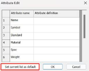
Custom symbols now support setting the default properties of the attributes.
In addition, when inserting non-parametric symbols from the library into the current drawing, the selected symbol is directly displayed in the property panel.
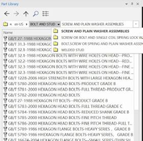
The Library can also be set to a hierarchical directory in the address bar and you can click to jump to subfolders. When you return to the parent directory, you are automatically positioned to the previously selected location.
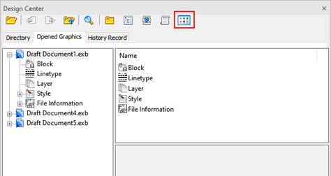
Design Center List/Thumbnail Display Functionality
In the Design Center, users can toggle between thumbnail and list display.
Support for Editing OLE Objects Created in Other CAD Software
OLE graphics created and inserted into documents such as Office or from other CAD Software can now be double-clicked to launch CAXA DRAFT for graphical editing. This is supported once configured.
Support for Copy/Paste of CAD Data to and from Other Software (Such as AutoCAD)
Copying in AutoCAD now supports direct pasting into CAXA DRAFT. When pasting into AutoCAD, supported AutoCAD versions can be set by adjusting the CopyAsDwg variable value.
By adjusting the CopyCLSID value, OLE graphics from the CAXA DRAFT can be copied as OLE objects to software like Word. By setting the CopyGenTmpFile value to 1, CAXA DRAFT graphics can be directly copied to SolidWorks sketches.
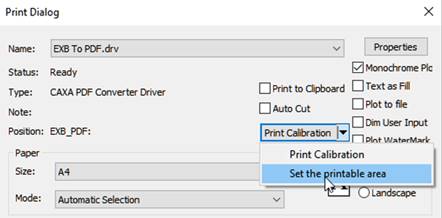
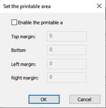
Printing Support for Printable Areas (Margin Settings)
The Plot/Print command now supports the ability to define a printable area.
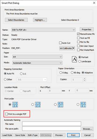
Smart Plot Support for Multiple Page Plot to Single PDF
The Smart Plot command has been improved to support Print to PDF, which allows print of multiple pages to a single PDF.
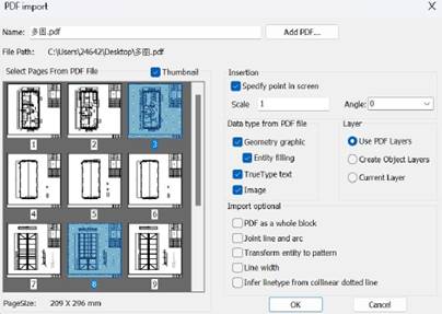
PDF Import Supports Multiple Page Import
PDF Import into CAXA DRAFT now supports multi-page import.
Print to PDF Improvements
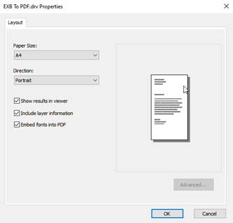
Using the Print driver EXB TO PDF, new options are available:
·“Text as Fill” is supported, and the text is printed to the PDF file as geometry
·Add the PDFSHX option to set the behavior after exporting PDF with SHX fonts
·The font data used can be embedded in PDF files in a subset to ensure consistent display
·Added a “Show results in viewer” control option, and print the PDF file with the default reader
·Added a Include layer information option to support the layer information for creating elements in the printed PDF file
Improvements in Print Output to Images
Print output of images has been improved for printing using EXB to PNG/JPG/TIF.
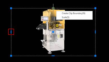
Insert Image Support for Handle Uniform Scaling and Clip Boundary
Inserted images now have midpoint handles that allow non-uniform scaling. In addition, a menu is available on hover of the midpoint to scale or create a clip boundary.
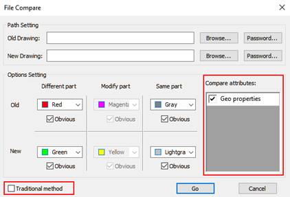
File Comparison Improvements for Comparison of Geometrical Data in DWG
The Compare Files tool can now compare attributes or geometrical data attributes. Use the toggle on the dialog to change between the two comparing methods.
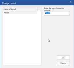
New Layout Switching Function with CTAB Command
The CTAB command supports selecting or inputting layout names to switch the current drawing space.
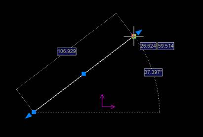
Dynamic Input Hover Display of Information for Grip Points
When the Dynamic Input option is enabled and the user hovers over a grip point, curve information will appear related to that point segment and the associated curve.
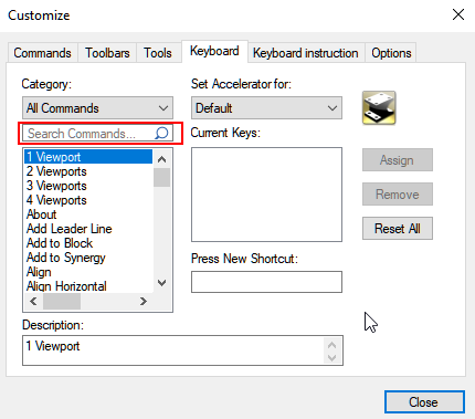
Search Command Added to Customization Keyboard Functionality
The Keyboard Customization tool has been enhanced to allow for searching of Keyboard Commands.
System Options Added to Command Line Commands
Command line support for system options has been added. Supported options include CursorSize, BigCursor, WinCursor, DragDelayTime, PICKADD, PickStyle, GroupDisplayMode, MIRRTEXT, and more.
Collaboration in Import/Export, Viewing, Rendering, and Design Sharing
IronCAD Native Translator, support for the latest file types
The IronCAD Native Translator Add-on extension has been updated to support the latest file formats from several of the most common 3D CAD systems on the market. Import now supports;
·CATIA V5: V5R8 – V5–6R2024
·Pro/E (CREO): 16 – Creo 10.0
·UG NX: 11 – NX 2306
·Inventor: V11 – V2024
·SolidWorks: 98 – 2024
·SolidEdge: V18 – SE 2023
·JT Import: 8 – 10.2, 10.3, 10.517, 10.618, and 10.718
·IFC: IFC 2×3, IFC 4
·Rhino: V2-7
·DXF/DWG: 2.5 – 2024
New IronCAD Architectural & Viewing Translator (Coming Q1 2024)
A new translator add-on option will be available for additional BIM format import/export and Graphical Formats. These include:
·IFC Reader/Writer
·Revit Reader/Writer
·GLTF Writer
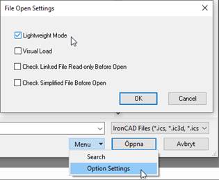
Open the 3D Scene as “Lightweight” (facet data only) for Viewing
A new option, Lightweight Mode, accessed via Option Settings in the Open window, can now open an IRONCAD 3D scene file (*.ics) as a lightweight model. The entire file structure will then open as facet data for viewing.
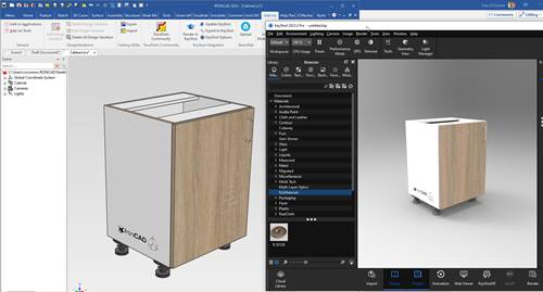
KeyShot for IronCAD Improvements
The KeyShot for IronCAD Integration has been improved in the following two areas:
·Image Scaling Properly Scales to Match IronCAD’s Textures
·Support for Decal Transfer from IronCAD to KeyShot
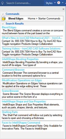
Search for Commands Expanded Search to Help System and Related Topics
The SearchCommand behavior has been improved to give users more relevant information on a searched topic. Not only do you get the command, you now get options about the searched item in the IronCAD Help and other relevant locations.
Synergy Collaboration Platform
IronCAD Synergy Collaboration Platform continues to improve the collaboration access and usability among IronCAD designers.
·Performance Improvements with Upload/Download during data transfer.
·Invite Collaboration Users from Other Synergy Accounts using the Collaboration User accounts.
·Invite Non-Synergy Collaboration Users to collaborate in your Synergy Account by giving a Collaboration User account access.
·Folder Structure Support in IronCAD Synergy Client to support multiple Synergy Account logins and data used in each system.