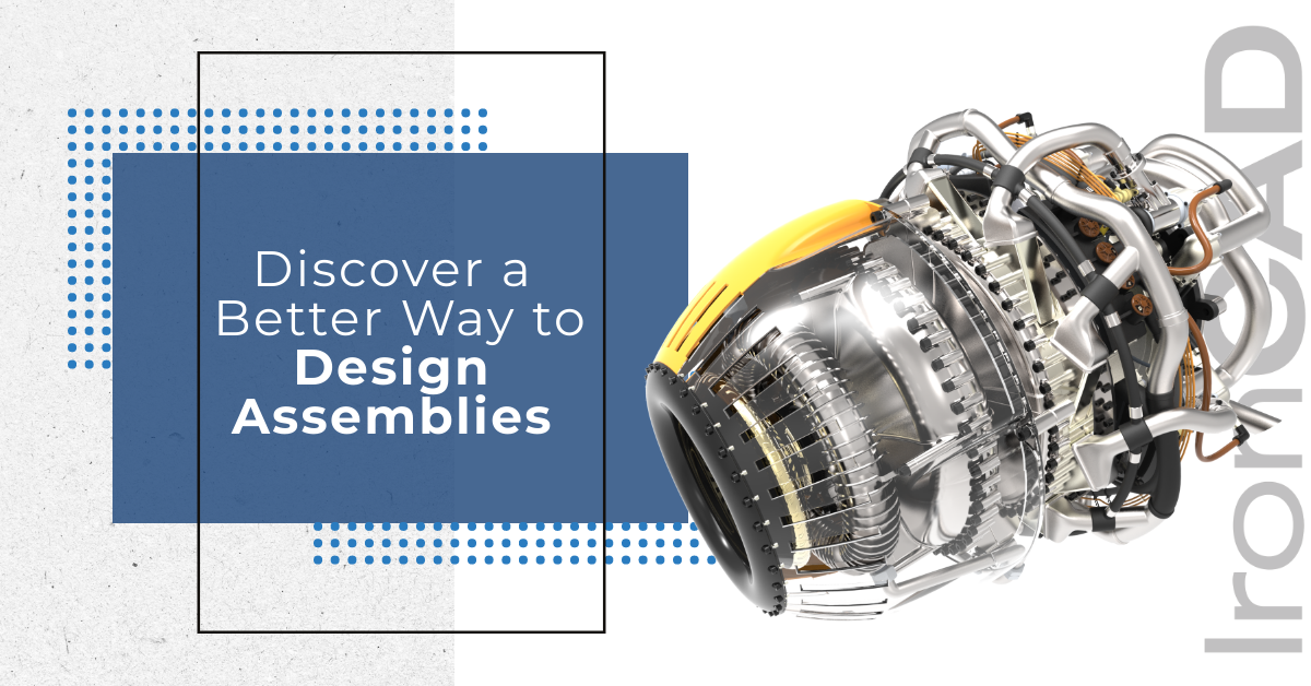
Discover a Better Way to Design Assemblies with Flexible 3D CAD Tools
Aug 19, 2020 |

Effective product design involves a wide range of tasks that demand flexibility in your software. 3D CAD modeling offers several advantages over traditional 2D design. Still, you want 3D CAD tools that you can use every day while being powerful enough to handle all the aspects of your design process.
With traditional CAD design systems, which create assemblies out of separate part files, it becomes nearly impossible to make any fundamental changes to a CAD assembly structure without also modifying constituent part files, re-linking to the assembly file, and then re-mating parts within the assembly.
With IronCAD, you get an intuitive 3D CAD system with a flexible design structure that combines ease-of-use with powerful modeling capabilities to handle your most complex design projects. IronCAD accelerates your design, saving you time and development costs, and making you more productive.
IronCAD’s capabilities include:
- Bottom-up or top-down assembly design with IronCAD, it’s your choice
- Build 1 part or 1 million parts all in the same file, you don’t need all the part files and data management systems
- Positioning assemblies with ease using the patented TriBall design to work in 3D space
- Configurations – allow for different versions of an assembly in the same scene.
- Reuse parts in multiple assemblies and automatically update when changes occur
- Create separate technical drawings for every part and assembly or selected parts/assemblies using IronCAD’s automated bulk drawing tool
- Reduce drawing time using common components and automated drawings to replicate drawing sheets in new projects.
Click the video below to learn more about IronCAD’s capabilities.
A traditional approach to building CAD assembly files is to start with a group of preexisting parts. These parts live in their own files, which are then linked into the assembly file. The assembly itself is built in the 3D environment through a tedious mating process that joins these constituent part files.
While this makes sense from a certain perspective (e.g., during manufacturing the assembly will, in fact, be built out of parts), this setup limits a user’s ability to work on the assembly in its entirety and stunts assembly design work. Making assembly structure changes becomes difficult as well as making positional changes of an assembly or groups of assemblies.
IronCAD lets designers decide which approach they want to take thanks to its Unified Design Environment, where part and assembly files are treated essentially the same. You can design in the context of a multi-part assembly comprising hundreds, thousands, or even hundreds of thousands of parts. The structure is flexible and is really a simple concept of grouping and ungrouping. If you want to change an isolated part file and re-link your assembly to it or change the assembly it is located in, you can do that, too with ease. Even build intelligent rules to reuse assemblies so that they can automatically position, orient, and size based on geometry it is connected to.
Whether you are working with 10 or 100,000 parts, making assemblies, manipulating structure, positioning, and detailing should be simple in today’s CAD systems. While many CAD platforms today have recognized the value of their users’ place on this sort of design environment flexibility, all of them have either attempted to add it on top of their core functionality or don’t offer a complete integrated solution. In the case of IronCAD, its Unified Design Environment is inherent to the logic of the desktop program. So there are no complicated workarounds — just the freedom to set up and manage CAD assembly files in a way that suits how you want to work.
