What’s New in 2018 Product Update #1
May 13, 2018 |
IronCAD 2018 Product Update #1 Release
We’re excited to announce our latest release, IronCAD 2018 Product Update #1. This update extends powerful functionality added in 2018 in addition to many usability improvements to increase design productivity in your design process. Below are more specific details about the productivity enhancements for 2018 Product Update #1.
Quick Links
- Sharing & Collaboration
- Improved Usability
- General Improvements
- Sheet Metal Design Improvements
- Quick Production Drawings
- DRAFT Environment Improvements
Sharing & Collaboration
Shrink Wrap Utility Enhanced
Expanding on the 2018 release of the Shrink Wrap utility, Product Update #1 adds many advance options and better display capabilities to preview the shrink wrap results based off the settings selected. The following improvements/options have been added:
- Shell Boundary – Gives an option to create only a shell representation of the model. This is a non-solid surface representation for better security and potentially smaller file sizes.
- Bounding Box Representation – Allows users to set various parts to a bounding box representation to better protect IP while indicating objects in a particular location instead of sending full details of the parts.
- Setting for “Do not include in BOM” – In the saved ICS file resulting from the shrink wrap command, you can turn off the “include in BOM: setting on the properties browsers so that this shrink wrap file will not appear in the BOM generated in the drawings.
- Set Mass – For the exported objects, set the User Set mass to the real model mass so that whoever the ICS is shared with can have an accurate mass calculation versus the shrink wrap mass which would be based off of the resulting shrink wrap mass size.
- Process Indicator – When hitting apply, a process indicator of what is happening and what percentage of the process is at will be displayed.
- Results – At the end of the process, a display of the result from the shrink wrap is presented. It provides success/failure information as well as final file size reduction and number of parts/features removed.
- Part Visibility Slider – Ability to adjust the visibility setting for Hiding Internal Parts. With a slider, you could adjust the accuracy of the viewing area and speed up the shrink wrap process.
- Feature/Face Exclude – New options are available to exclude features by selecting faces making up the features. This allows more precise control in the feature removal process to eliminate specific face sets such as holes versus removing by the hole size settings.
- Better Support for Surface Geometry – Ability to support hole removal on surface geometry that could come from imported data or IronCAD surface parts.
- Preview for Feature/Parts Removed – Two preview options have been added to allow a preview for the parts that will be removed and one for features that will be removed. These help visualize the result prior to running the command.
Available in:
Support for Latest Translator Formats
IronCAD’s Native Translators have been updated to support the latest improvements and newer native formats. With the latest release of the IronCAD DCS, you will have access to the following versions of CAD file formats using our Native Translators.
- Inventor: V11 – V2018
- SolidWorks: 98 – 2018
- SolidEdge: V18 – ST10
Available in:
Improved Usability
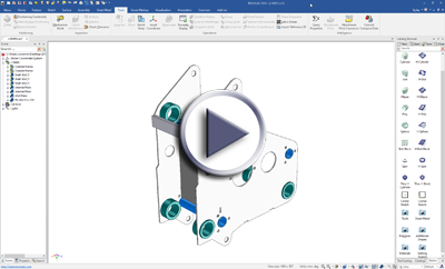
Extrude New Feature Handle on Planar Faces and Sketches
To improve productivity when creating extruded features, a new handle has been added to planar faces and sketches that grants the ability to push/pull to create a new feature from the face/sketch (positive or negative). This is a quick command to start a new feature from existing geometry. For 2D sketches, the handle will start a new part when pulled.
Available in:
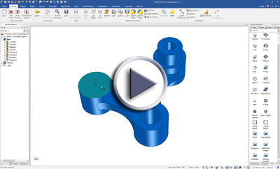
Extrude Profile Handle Positive/Negative Pull
Profile extrude handles can push and pull through the shape to toggle positive or negative extrude. For example: Drop an H-cylinder on a part and select the profile extrude handle. Pull in the opposite direction past the start profile and it will become a positive boss shape.
Available in:
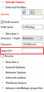
Extrude Direction
The Extrude Feature now has an option to extrude along a defined (or selected) direction.
Available in:
4K Monitor Improvements
Some minor improvements have been implemented along our path to better support high-resolution monitors. These changes include:
- If the Windows OS is 8 or greater, it will default the option to DirectX11 as the default rendering engine. OpenGL2 is not supported well on the newer operating systems since the focus has been on Direct X.
- Box Selection is supported in the scene and ICD.
- Shadows on right-click menus and Quick Access toolbars are removed to avoid display issues.
Available in:
UI Ribbons, Starter Catalog, and Shortcuts Updated
Updates have been made to the ribbon bars and Starter Catalog to make them more user friendly. Easily locate starting commands on the Home Ribbon and browse new shapes available in the Starter Catalog to get you started with a simple drag and drop. In addition, new keyboard shortcuts have been added and can be located in the Help under Function Key Reference.
Available in:
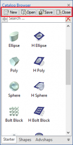
Catalog Buttons for Ease of Use
New Buttons have been added on top of the catalog to make it clearer how one can create new, open, save, and close catalogs.
Available in:
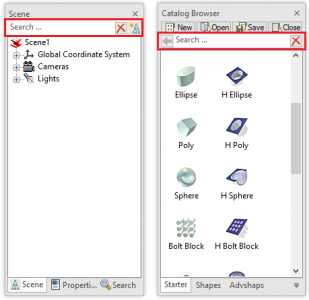
Search … Text
Text strings have been added to the Catalog and Scene Browser “search” areas to make it clear that these areas are for quick search. Simply locate these areas and type to quickly search/filter the displayed browser contents.
Available in:
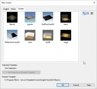
Preview of Scene Templates
When creating a new scenes, the template selection dialog will now display preview images of the available templates. This aids in the process of selecting the appropriate template versus the previous name-based selection.
Available in:
General Improvements
Pin/Slot Constraint
In the Positioning Constraints command, a new type of constraint has been added for a Pin/Slot. This will allow an object like a shaft to be constrained to a slot’s centerline and the length of the slot. This allows the movement of the shaft in the mechanism mode or parametrically solves to maintain the relationship to the slot.
Available in:
Attachment Point Connector
A new tool to allow connection point changes from a source to a new location. Typically, when the connection was made on drop with Smart Assembly and when using constraints with the attachment points, it was difficult to reconnect to a new location. The new tool allows these reconnections to take place by a simple pick-pick process. This tool was designed to work with attachments that have constraints applied. With constraints, the tool will detect, disconnect, and reconnect the constraints to the new location.
Available in:
Smart eBehavior Parallel Contraint
New constraint types have been added in the Smart eBehaviors. Parallel constraints are now available to provide additional control and behavior. For example: If you have a keyway that you would like a pin to slide along and maintain its orientation in the keyway, the parallel constraint used in conjunction with the coaxial constraint can solve this behavior. Simply add the options to the attachment point name and you will get the desired behavior on drop.
Available in:
Sheet Metal Design Improvements
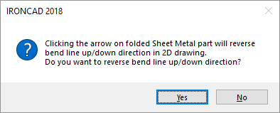
Warning for Sheet Metal Arrow Toggle
A new warning has been added to the sheet metal part direction arrow. When the arrow is clicked, the warning is displayed to explain the results of changing the arrow direction. This can help prevent the accidental bend direction flipping on the drawing.
 Available in:
Auto-Associate Reconnection
In the past, if you broke the sheet metal association on bends and stocks at the sketch level, you could not reconnect or recreate the association. Now when this occurs, you can simply right-click on the bend handle and reconnect.
Available in:
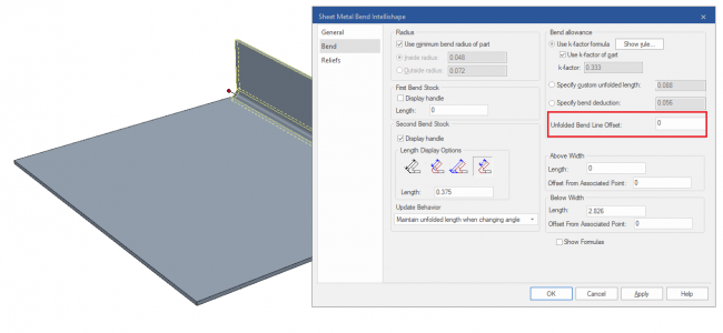
Offset Value for Sheet Metal Bend Lines
A new option has been added per bend to allow offset of the bend line (+ or –). This is used in some folding operations where the bend line needs to be offset for the particular type of unfold operation such as corrugated packaging.
Available in:
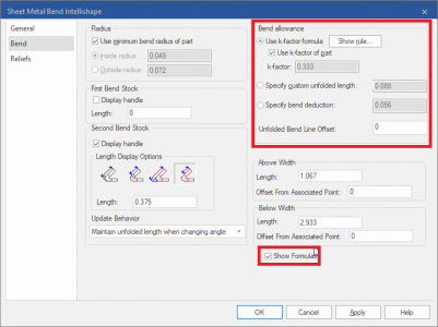
Parametric Formula Support for Bend Allowance
The bend allowance and bend deduction can now be parametrically controlled.
Available in:
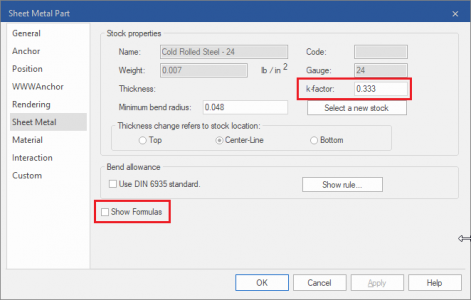
Parametric Formula Support for K-Factor
The k-factor for sheet metal parts can now be controlled using parameters via the Show Formula option. This allows parametric expressions to drive behavior in the sheet metal.
Available in:
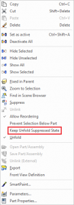
Sheet Metal Unfold Option to Remember Unsuppressed Items
A new option has been added to sheet metal unfolded parts on the right-click properties menu to “Keep Unfold Suppressed State” which allows you to unsuppress other parts and maintain this visibility when future unfolds are called on the part. In many cases, other objects may need to be unsuppressed to be called out on the drawing in the unfold state. This option supports that behavior.
Available in:
Bend Properties Opens to Correct Dialog
When selecting to a bend Intellishape and right-clicking to access properties, the resulting dialog will open directly to the Bend properties dialog versus the general dialog page.
Available in:
Quick Production Drawings
Bulk Creation User Experience Improvements
Improvements have been made in the Bulk Creation workflow to make it easier to apply/assign geometry to be used in the Bulk Drawing Creation wizard. When selecting Parts/Assemblies, the property browser now has options to “include” the selection in the Bulk Creation and select the Default template to be used. Additionally, parts have options to apply the front view direction or to tell visually if it has been already applied. Templates can also be added to the Bulk Creation Drop Down in the Property Browser to dynamically add templates when needed.
Available in:
Bulk Creation Auto Scale
A new option that is a massive time saver has been added to auto-scale the geometry to the selected template layout during Bulk Creation. View Templates allows you to create the view layouts based on a view scale of the reference model. This new option, located in the Tools/Options/Technical Drawing enables auto scaling of the parts selected in the scene that use these templates as part of the Bulk Creation process. This scales the parts to fit on the template’s bounding box area that was already set without any changes required. Essentially, this new option only requires a single template — or very few view templates — and can auto scale the parts/assemblies to fit, which reduces the complexity in the current templates based on set view scale sizes.
Available in:
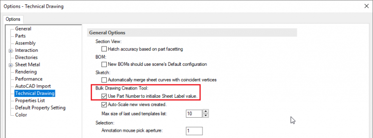
Bulk Creation Sheet Label Use Part Number
Another useful option has been added to the Tools/Options/Technical Drawing to dynamically set the Sheet Name based on the Part Number defined on each Part/Assembly. This can reduce extra time spent renaming the sheets in the Bulk Creation Tool.
Available in:
Bulk Creation Folders
The Bulk Creation folders delivered with IronCAD are now clearly identified with “Bulk” in the folder name.
Available in:
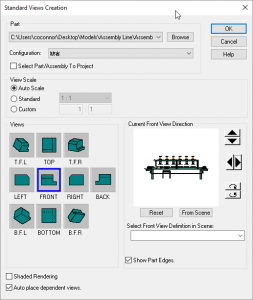
Preset Front View
When creating new drawings and standard views, the Front View is now pre-selected. This saves time when creating simple front views on new drawing/sheets.
Available in:
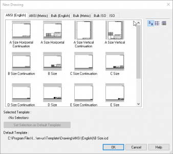
Preview of Drawing Templates
When creating a new drawing, the template selection dialog will now display preview images of the available templates. This aids in the process of selecting the appropriate template versus the previous name-based selection.
Available in:
DRAFT Environment Improvements
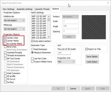
Draft Support for Arc Centermarks on Creation
Similar to ICD, the DRAFT environment will create centermarks for arcs such as projected blends. This is a new option in the projection dialog that can control centermark creation for circles and arcs independently.
Available in: