What’s New in IronCAD Design Collaboration Suite 2022!
Nov 15, 2021 |
IronCAD Design Collaboration Suite 2022
Improving Detail Drawings and 3D Design Productivity
We’re excited to announce the latest release of IRONCAD 2022, which focuses on productivity by making your innovative 3D designs go to production faster. This new release contains many exciting improvements and capabilities that help you drive innovation. Our goal for IRONCAD 2022 was to focus on improving 2D detailing, improving the user experience, continuous quality improvements, and improvements that make the design process more productive.
Below are more specific details about this release and focuses specifically on the following areas:
Quick Links
- 2D Detailing in IronCAD Drawing Improvements
- General Modeling and User Interface Improvements
- Design Process Improvements
- Sheet Metal Design Improvements
- Intelligent Design Updates
- CAXA DRAFT Drawing Updates
- Application Updates Updates
- Component and Collaboration Updates
2D Detailing in IronCAD Drawing Improvements
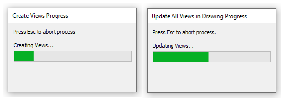
Progress Bar on Long Operations
A Progress bar has been implemented to better show the progress of the current operations, like View Creation, View Update, change to Shaded Views, change to Precise Views, etc.
Available in:
Press [Esc] to Exit View Creation or Other Long Process Commands
With the introduction of the Progress Bar, it is now also possible to cancel many operations where you previously had to wait until it was finished. Simply press the ESC Key in these process dialogs to exit out of the process.
Available in:
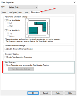
Auto Dimension Support for Bulk View Creation Template
The Auto Dimension tool can be set on a per-view basis in templates used for the Bulk View Creation to automatically create dimensions when creating drawings. This is a useful capability to quickly apply dimension on views along with the other options already supported in the Bulk View Creation Process.
Available in:
Box Select Creation of Ordinate Dimensions
During the Ordinate Dimension command, you can now box select areas to place ordinate dimensions to speed up the detailing process.
Available in:
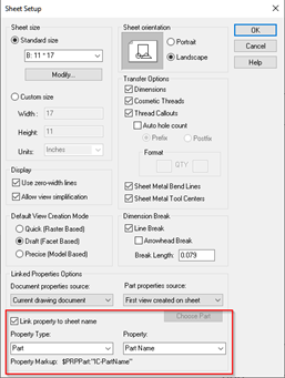
Link Sheet Label to Scene/Document Properties
New ability to associate properties to the sheet name in ICD is now available to automatically define sheet names based on the content in the drawing. This new capability can be found on the Sheet Setup in the IronCAD Drawing Environment.
Available in:
Magnify Glass Support for Annotating Smaller Areas
A new magnifying glass behavior has been added to the IronCAD Drawing Environment to improve the ability to annotate smaller areas of the drawing views that would normally require zoom in/out processes. Simply press the hotkey “G” to magnify the area around the current cursor location that will allow precise highlight and selection on the zoomed-in area.
Available in:
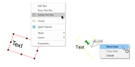
Easy Rotation of Text in Properties
A new option has been added under the right-click menu of TextBoxes. Hold down the right mouse button, to rotate and then release to get an option to set an exact angle value. As usual, the left mouse button will not give you those options and simply rotate.
Available in:
Rotation Point of Text in Properties Default at Center
The rotation point for TextBoxes has been changed to default to the center of the box, making it easier to perform a rotation.
Available in:
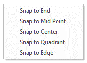
Easy “Snap To” When Dimensioning
When dimensioning, especially on a small area or zoomed-out areas, it is sometimes difficult to select the desired entity point. In the dimension command, you can select the “Spacebar” to provide snap settings to End Points, Centerpoint’s, Quadrants, Mid-Points, and Edges.
Available in:
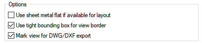
Mark Views for DWG/DWF Export Only
In many cases, you may want the ability to have more control with DWG/DXF exporting. For example, when working on large drawings for laser cutting, you may want to exclude certain views from the export process. Now you can set desired views that will only export when using the Export to DWG/DXF command. This option can be found on the View Properties page.
Available in:
Improvements on Move Performance of Many Sheet Curves
When selecting and moving many sheet curves in the IronCAD Drawing Environment, the performance has been improved on the grouped and ungrouped curves during the drag and move behaviors.
Available in:
Move Dimension After Creation While Within the Dimension Command
While in the Dimension command and after you have placed your dimension, Left-click on the highlighted red Dimension Arrow (line end) or the Dimension Text to “enter edit mode”. Click and drag the dimension to the new location, click again to place.
Available in:
Multi-select Dimensions for Quick Editing in the Property Browser
It is now possible to have more than one single Smart Dimension selected at once and edit the properties of those dimensions simultaneously through the Property Browser.
Available in:
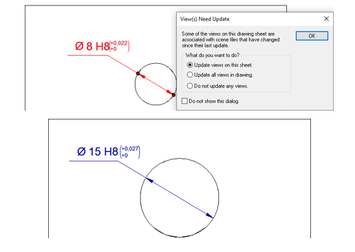
Tolerance and Fit, Dynamic Value Update
The tolerance values applied in the Tolerance and Fit now update automatically when the hole diameter changes to reflect the proper tolerance range based on the code.
Available in:
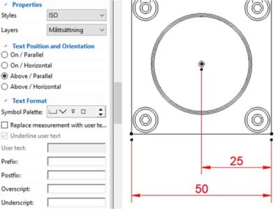
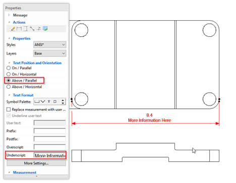
Dimension Underscript in Combination with “Above” Support
The Smart Dimension Underscript text can now be placed below the dimension line, when no
Overscript text has been set to give a properly displayed result.
Available in:
Reference Intersection Support for Centerline Reference
The Reference Intersection tool can now refer to centerlines to define the reference intersection. This is useful in pipework where you want the intersection of the centerlines to place dimensions. With this new capability, you can create the intersection and place the dimension on the reference location. When the geometry changes, the centerlines will update along with the reference intersection.
Available in:
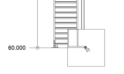
New Support for Elevation Dimensions Based on the 3D Scene Location
Provide a new option on the origin of the Ordinate Dimension to set the value with respect to the scene origin location. For certain designs, the original location of the model may not be 0 but maybe a value like 240’ (as the point selected for the origin is 240’ from the scene origin along the global Z-direction). Using the Ordinate Dimension, you can right-click on the origin and select “Use as Elevation” to pull the distance value from the scene origin in the current view direction.
Available in:
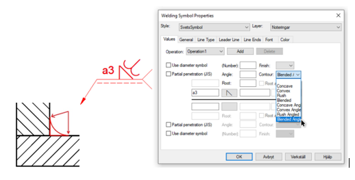
Welding Symbol – Blended Angle Contour Support
The contour symbol Blended Angled has been added to the list of contour options in the Weld Symbol. The symbol is being used for a smooth transition in socket edge, when the “end of the toe” of the weld shape needs to have a “smooth transition” to the adjacent face.
Available in:
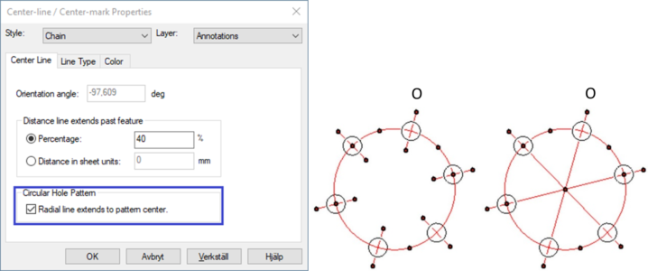
Circular Hole Pattern Annotation Options to Hide the Radial Lines
A new option has been added to control the length of the inner radial lines.
Available in:
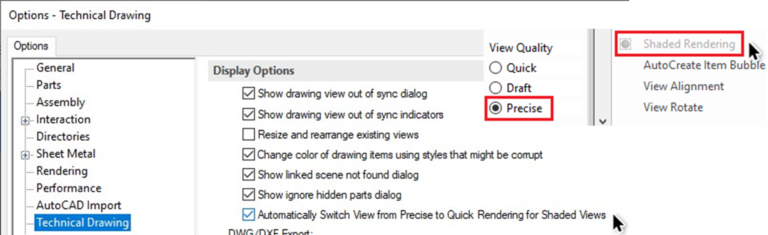
Shaded Rendered View Auto Switch View Mode for Precise Views
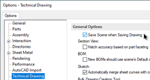
Views using the Precise Mode view type cannot be shown with colors and textures (also called Shaded Rendering). The Shaded Rendering option is now active also for Precise Mode views but using the shading will also change the view to using the Quick Mode view type instead.
The setting is not active by default and can be found under Options, Technical Drawing.
Available in:
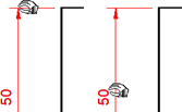
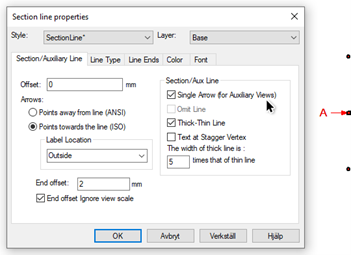
Support for a Single Arrow with a Reference Letter for Auxiliary View (and Projected View)
A new option has been added to support the use of a single arrow as a reference for Auxiliary and Projected views. Placement options under the Label Location are added to help orient the Label with respect to the arrow location.
Available in:
Save Drawing Without Saving Modified Scene
A new option has been added under Options, Technical Drawing to control whether the Drawing and the Scene should be saved at the same time when saving the Drawing (in the case where the scene is in a modified state). In case only metadata in the Drawing Header for example has been changed, the Drawing can be saved without affecting the last saved date or other unwanted changes of the Scene.
Available in:
Detail View Refers to Face Geometry Location
In previous versions, the detail would associate a point that would be selected in the definition of the detail circle. Thus if the geometry updated and the point moved, the detail view would move as well. If the Centerpoint was defined on a face, there would be no association and the detail view could become disoriented on update. Now in 2022, the location on the face will be remembered and the detail view will move when that location moves on an update to provide a more consistent result.
Available in:
BOM, Tables, Revision, Hole Table, and DV Table More Consistent
Updates have been made to the display and consistency of the tables used in the IronCAD Drawing Environment. The interface will now have similar commands across all tables to make it more convenient for users to use.
Available in:
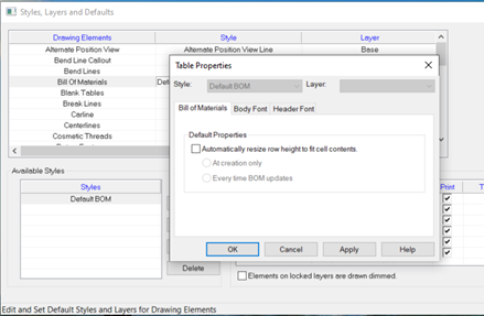
BOM with Automatic Row Height Adjustment
A new property has been added to the BOM that every time the BOM is updated, it will adjust the row height based on contents in the cells. Users can turn off this property via the BOM property page. Note that there are two default options for the Auto Row Height setting: to apply Auto Height only at creation, and to apply Auto Height for all updates. If the user chooses to only apply Auto Height at creation, then the property to apply auto height for every update will of course be unchecked on the BOM property page.
Available in:
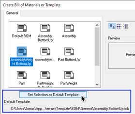
Set Selection as Default Template for the BOM
A new option to set the selected BOM template as the default, saving a few clicks every time the BOM is being created.
Available in:
Rectangular Split Item Bubble Support
A new Item Bubble type has been added for split rectangular when using Upper and Lower BOM values.
Available in:
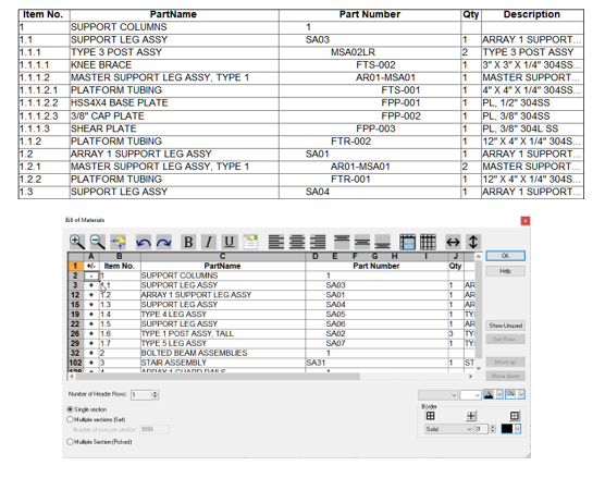
Structured BOM Table Support with Expand/Collapse Row Capabilities
Users want the ability to expand and collapse the rows in a BOM in order to hide the children of an assembly. A new BOM type has been added called “Structured” to support a new item style and the ability to manually control the expansion or collapsed state of the BOM.
Available in:
General Modeling and User Interface Improvements
3D Rotation Improvement About Center
Improvements have been made to the 3D Rotation using the Middle Mouse button in the 3D Scene to rotate about the scene center when the cursor is located in space. Previously, the rotation will rotate about the object the cursor is located on. If it was in space, it would use the last set rotation “about” location which could cause the scene to rotate about an arbitrary location at times. Now it will calculate the object and the scene center to rotate about to give a much more predictable rotation result.
Available in:
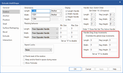
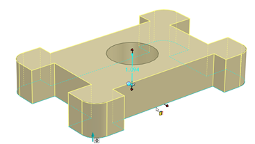
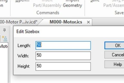
SizeBox Handle Drag Limit Options
New controls have been added to the SizeBox properties to set limits on the drag size. This is a useful feature to control the behavior of shapes that may have limits on the design size. Simply set the upper and lower limits and the drag will stop when that limit is reached. Editing the SizeBox value edits (or parameter edits) will not be limited in this release.
Available in:
SizeBox Snap Setting Remembered Per Shape
Now you can control the desired snap increments per shape at the SizeBox level. This is great to have different behaviors for a different object that may have controlled sizes as it is dragged.
Available in:
Mass Calculation for Multiple Select Objects
Users can now multi-select parts/assemblies in the scene or scene browser and access the mass calculation of the selection in the property browser. This is useful to get a quick mass calculation of the selected objects.
Available in:
Maintain Active Handle Control on Profile Handles
When working with Profile Handles, the handle display toggles to the curve your cursor is currently over. However, in cases where the curves are near each other, the handle could toggle off when you are trying to reach and edit it. Now you can simply hold the Ctrl key down when the desired handle is displayed and it will remain active until the Ctrl is released.
Available in:
Lock Edited Handle on Profile Handles
When editing Profile Handles (for example: Setting the Snap Point or Handle Orientation), you often would find that it would reset as soon as another curve is touched by your cursor. To prevent this, once Handle Snap Location or Orientation is set, the current handle will remain active until clicking off the shape or hitting the ESC key to release the lock.
Available in:
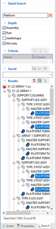
Search Browser Support for Shift/Ctrl Multi-Select in Results
Using the Search Browser is now even better as you can multi-select in the results tree. Using the Ctrl to individually multi-select and the Shift to Select All between the Top/Bottom selections, you can now make better use of the search tree to locate and work on the results.
Available in:
User Interface Update to Remember Dialog Location and Default Location
The user interface has been improved in this release to remember the last placed location of dialogs. By Default, most dialogs like property dialogs, Command dialogs, and wizards will initiate in the scene upper left corner. You can drag any dialog to a new location and it will remember that location for future reference to help reduce mouse movement and to provide the optimal working environment for each user’s needs.
Available in:
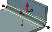
Performance on Editing Features – Optional Display Transparency
While editing modification features, other parts are shown transparently to better illustrate that they are not affected by the changes of the feature.
![]()
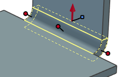
Due to its possible bad effect on the graphical performance, transparency should be avoided in larger assemblies. The new setting will not show other parts transparently while editing the feature settings.
![]()
Available in:
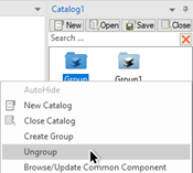
UnGroup Command on Grouped Catalog Containers
A new option has been added to the right-click menu of the Group icons in Catalogs to ungroup the content and place it at the top level, parallel to the existing content of the selected group.
Available in:
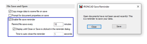
Save Reminder Support for Time Displayed, Force to Close, and Save Option
A new option to display a Close (the reminder) and a Save (the active scene) button within the Save Reminder window has been added. In case of the Close & Save setting is not active, a timer can be set for the time the window should be shown before automatically closing.
Available in:
Design Process Improvements
3D Curve Creation Update for X,Y,Z Orientation Control
When creating a 3D Curve in space, it is useful to have orientation control to define the plane to create curves. Now you can perform this in the IronCAD 3D curve and toggle the plane definition with a tab key.
Available in:
3D Curve Additional Curve Type Support
With the new curve creation capabilities, the 3D Curve creation and editing types have been updated to support similar capabilities found in the 2D Sketch.
Available in:
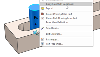
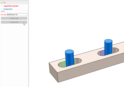
Copy/Link Object with Constraints to New Reference
A new command has been added to the right-click menu of shapes with constraints to allow Copy/Link with Constraints. This will copy the geometry and the constraint and assign it to the new reference geometry.
Available in:
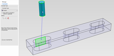
Pin-Slot Contraint to Middle of Slot
Users want to have an option to lock a pin to the middle of the slot for pin-slot constraints. A new option (Lock to MidPoint) is added to the locked pin-slot constraint in the Position Constraints command. The option will be shown only for locked pin-slot constraints.
Available in:
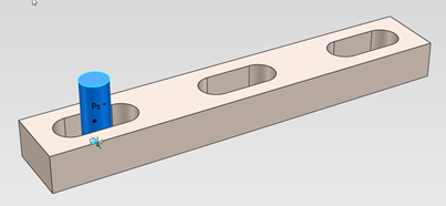
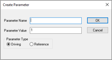
New Direct Parameter Creation from SizeBox Handles
New right-click option on SizeBox handles to quickly create parameters (driven or driving) that reduce the many steps currently needed today. You can create a driving parameter with an assigned name and value or a driving parameter with a name that pulls the current handle’s value.
Available in:
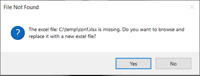
Find Missing Excel Path for Parameter Table
New options to allow users to browse and replace missing excel paths for parameter tables. When a part or assembly with a parameter table that has a missing excel path is opened, a “File Not Found” dialog will pop up and allow the user to browse and replace missing excel files, or user can choose to skip.
Available in:
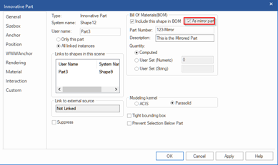
Mirrored Linked Part/Assembly Unique Part Number Capability
When creating linked mirrored parts/assemblies, users will want to have unique part numbers to properly identify the mirrored parts. In the Properties dialog for BOM settings, a new option is enabled on mirrored parts/assemblies to allow you to set a unique part number and description for the shape.
Available in:
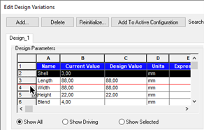
Reorder Design Variation Rows
Hold down the left mouse button on the row and drag to the new location. A red horizontal line shows the location of the new position when dropped.
Available in:
Sheet Metal Design Improvements
Support for Edit Feature/Edit Sketch Hotkey in Sketch Bend
The standard hotkey assignments for Edit Feature (E) and Edit Sketch (Alt-E) now work for Sketch Bend features as well.
Available in:
Support for Multi-Select Bend Handles (Symmetrical Modification)
Bend Shapes has added support to Ctrl select both handles to perform a symmetrical size operation. This will continue to work with the multiple bends and Bend handle selection to perform the change on multiple bends at one time.
Available in:
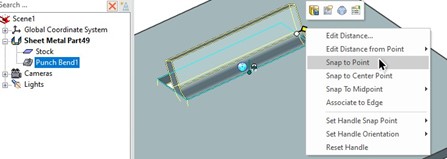
Punch Bend Support to Show Profile Dimensions on Selection
Shape handles on the sketch make it easy to edit the size of the Punch bend shape now in 2022. In addition, the sketch constraint dimension will be shown as well to enable direct editing.
Available in:
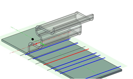
Sketch Bend Preview Support
When the option Fixed Geometry has been set and bend lines added, a preview of the Sketched Bend will be shown. The preview is dynamic and will update when settings are changed.
Available in:
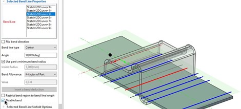
Sketch Bend Tools For Debugging – Disable Bend
A new option has been added to disable and enable individual bend shapes within the Sketched Bend settings.
Available in:
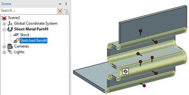
Sketch Bend Handles in Folded State for Easier Editing
Handles are now shown in the folded state on the selected Sketch Bend to allow easier modification of sketch bend shapes.
Available in:
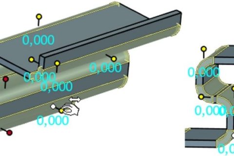
Move Multiple Sketch Bends at Once
Hold down the [Ctrl] key and select more than one Sketched Bend Shape handle.
Available in:
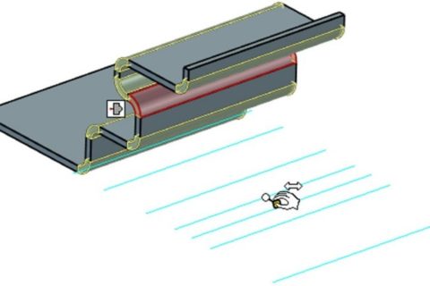
Sketch Bend Profile Handle Identification to Folded Bend Result
When placing the cursor over a Bend Shape handle on the sketch, the Bend Shape geometry will highlight in red to identify the resulting bend from the sketch line.
Available in:
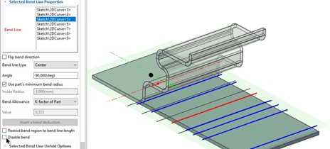
UI Improvement for Bend Radius and Bend Angle Handles
Color assignments have been added for Bend Radius and Bend Angles to help identify them, especially in small bend cases. Also in the Tools/Options/Sheetmetal, you can disable the Bend Handles or just the First Bend Handle to display the desired editing handles. The two Bend Angle Handles now use two different colors ->Orange (First Bend Angle) and Blue (Second Bend Angle).
It is now also possible to only display the Second Bend Angle handle with an option.

Available in:
Intelligent Design
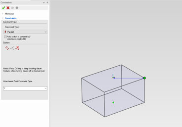
Attachment Point Dimension Constraint Support
When creating a positioning constraint, if the first entity is an attachment point, then a class of constraints that drives the position or direction of an attachment point will be created. Once the constraint is created, the position or direction of the attachment point will be driven by the second entity selected in the constraint. Support for various types of constraints such as coincide/concentric/parallel/perpendicular/tangent/distance/angle/follower/cam depending on the selection of origin or x, y, z-axis of the attachment point.
Available in:
CAXA DRAFT Drawing Improvements
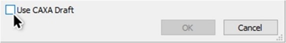
Bulk View Creation CAXA DRAFT Setting Remembered
In Bulk View Creation (BVC), the dialog in the 3D Scene will remember the Use CAXA Draft setting so that it can default when using the BVC tool.
Available in:
Setting Templates for Bulk View Creation Support for DRAFT Templates
In the Property Browser, you can add default templates to Parts/Assemblies for both ICD and CAXA Draft Templates.
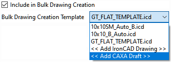
Available in:
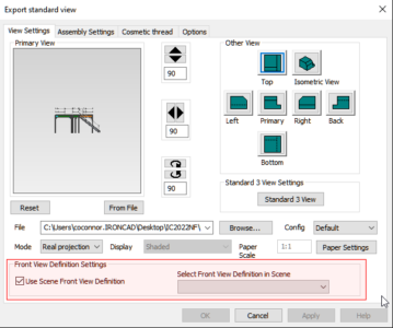
Front View Definition Support in CAXA DRAFT View Creation
Front View Definition has been added to the View Creation Dialog to create views using this setting on the 3D Parts/Assemblies and to define templates for the BVC.
Available in:
Performance Improvements in DRAFT
Performance Improvement on Large Data Sets (many parts/assemblies) on selection and Interaction has been improved to provide a smooth interactive experience.
Available in:
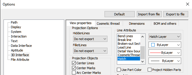
Hatch Global Settings
Ability to Set the Global Hatch Attributes Option Setting in Tools/Options for the application settings.
Available in:
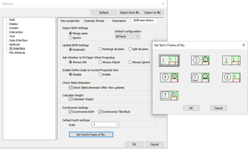
Global Item Bubble Setting Defaults
Ability to Set the Global Item Bubble Setting in Tools/Options Default Settings for creating Item Bubbles with the desired default type.
Available in:
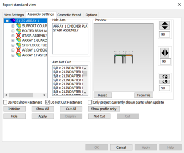
View Creation Dialog Improvements
Improvements in the Assembly Settings on the Standard View Creation to set Hide/Display and Cut/Not Cut Settings.
Available in:
General Quality Improvements Addressed
- Support ID 112437 – Center Marks are Scaling with Views should be resolved.
- Support ID 106052 – Hide Lines Return After Changing Hidden Lines should be resolved.
- Support ID 106064 – Purge doesn’t remove Table Styles should be resolved.
- Support ID 106020 – Table Vertical Margins Don’t Behave as Expected – More of a Note: Entering 5 is the word height of 5 lines of text, that is, the table will calculate the height of each line according to the word height and page margins in the table style. This should be consistent with ACAD’s behavior.
- Derivate Not Picking Existing Coordinate Origin should be resolved.
- Support ID 106049 – Modify Dimension Deletes Suffix should be resolved.
- CAXA – Deleted Center Marks Return should be resolved.Support ID 101933 – Layout Viewport scale problem with Ordinate dimensions should be resolved (or has been resolved).
Available in:
Application Updates
Touch Screen for Windows Improvements
The purpose of this functionality is to implement a way for the user to utilize a touch screen to interact and work with the basic mechanics of IronCAD. This functionality will only recognize the first two fingers that touch the screen in order to ensure proper gesture recognition. Because of the way Windows releases their API versions, this will not work on Windows 7 and instead will only work on Windows 8 or newer.
- Below is the added Gesture support
- Performing a pinch gesture in a scene will perform a zoom in/zoom out.
- Performing a two-finger drag will pan the scene
- Touching and holding with two fingers for a second will bring up a right-click menu upon release
- Tapping with one finger will do a normal scene selection
- Dragging with one finger will perform an orbit
- Holding CTRL while dragging will cause the program to not rotate and instead perform a click and drag operation, this is used mainly for handles and to prevent mistouches causing rotations. This is also used for adding sketches to the scene
Available in:
IronCAD Embedded Screen Recorder
Located in the Help Ribbon Bar, a new Record command is available to record the IronCAD application window and actions. Using the latest streaming capabilities, the generated AVI file will be compressed and support both video and audio. This capability is great when reporting questions to IronCAD Support team members or when wanting to record quick videos to share with clients and team members.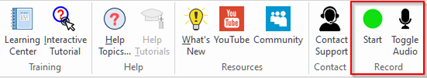
Available in:
Component and Collaboration Updates
Support for the Latest Translator Versions
IronCAD’s Native Translator has been updated to now support Rhino 7.0. Additional format support is listed below for formats such as SolidWorks, Inventor, Pro/E, Unigraphics, and Catia.
- CATIA V5: V5R8 – V5–6R2021
- Pro/E (CREO): 16 – Creo 7.0
- UG NX: 11 – NX 1953
- Inventor: V11 – V2022
- SolidWorks: 98 – 2021
- SolidEdge: V18 – SE 2021
- JT Import: 8 – 10.2, 10.3, and 10.5
- IFC: IFC2x3, IFC4
- Rhino: V2-7
Available in:
PMI Reference Data Import
New support to convert files with PMI to the IronCAD PMI data has now been added. When importing CATIA models, PMI data will be imported automatically without any setting modification. When importing other formats such as UG, ProE, SolidWorks, you will need to select the “Import PMI” in the import dialog. In IronCAD 2022, we support 5 types of PMI: dimension, surface roughness, text annotation, datum feature, and GD&T symbols.
Available in:
Multiphysics for IronCAD
Multiphysics for IronCAD has been updated to the latest version that includes new piezo-electrical material and updated the XMD version among many other improvements. Details will be shared in a blog post for Multiphysics for IronCAD 2022.
Available in:
IronCAD Mechanical
Updates to the latest version of IronCAD Mechanical including improvements to the View Manager, Part Numbering, Steels, ProActive BOM Manager, and many more. Details will be shared in a blog post for IronCAD Mechanical 2022.
Available in:
Sketch-Up Importer
Support for Sketch-Up import up to version 2021 using the current Sketch Up import option on the Add-in Ribbon bar.
Available in: